M30290FAHP#U5A Renesas Electronics America, M30290FAHP#U5A Datasheet - Page 113
M30290FAHP#U5A
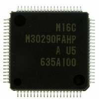
Manufacturer Part Number
M30290FAHP#U5A
Description
IC M16C/29 MCU FLASH 96K 80LQFP
Manufacturer
Renesas Electronics America
Series
M16C™ M16C/Tiny/29r
Datasheet
1.M30291FCHPU5A.pdf
(501 pages)
Specifications of M30290FAHP#U5A
Core Processor
M16C/60
Core Size
16-Bit
Speed
20MHz
Connectivity
CAN, I²C, IEBus, SIO, UART/USART
Peripherals
DMA, POR, PWM, Voltage Detect, WDT
Number Of I /o
71
Program Memory Size
96KB (96K x 8)
Program Memory Type
FLASH
Ram Size
8K x 8
Voltage - Supply (vcc/vdd)
2.7 V ~ 5.5 V
Data Converters
A/D 27x10b
Oscillator Type
Internal
Operating Temperature
-20°C ~ 85°C
Package / Case
80-LQFP
For Use With
R0K330290S000BE - KIT EVAL STARTER FOR M16C/29M30290T2-CPE - EMULATOR COMPACT M16C/26A/28/29M30290T2-CPE-HP - EMULATOR COMPACT FOR M16C/TINY
Lead Free Status / RoHS Status
Lead free / RoHS Compliant
Eeprom Size
-
Available stocks
Company
Part Number
Manufacturer
Quantity
Price

Part Number:
M30290FAHP#U5AM30290FAHP#D3
Manufacturer:
Renesas Electronics America
Quantity:
10 000
Part Number:
M30290FAHP#U5AM30290FAHP#U3A
Manufacturer:
Renesas Electronics America
Quantity:
135
Part Number:
M30290FAHP#U5AM30290FAHP#U3A
Manufacturer:
Renesas Electronics America
Quantity:
10 000


R
R
M
9.9 CAN0 Wake-up Interrupt
9.10 Address Match Interrupt
e
E
1
. v
J
Figure 9.13 CAN0 Wake-up Interrupt Block Diagram
6
0
CAN0 wake-up interrupt occurs when a falling edge is input to CRX. The CAN0 wake-up interrupt is en-
abled when the PortEn bit is set to 1 (CTX/CRX function) and Sleep bit is set to 1(Sleep mode enabled) in
the C0CTLR register. Figure 9.13 shows the block diagram of the CAN0 wake-up interrupt.
An address match interrupt request is generated immediately before executing the instruction at the ad-
dress indicated by the RMADi register (i=0 to 1). Set the start address of any instruction in the RMADi
register. Use bits AIER1 and AIER0 in the AIER register to enable or disable the interrupt. Note that the
address match interrupt is unaffected by the I flag and IPL. For address match interrupts, the value of the
PC that is saved to the stack area varies depending on the instruction being executed (refer to “Saving
Registers”).
(The value of the PC that is saved to the stack area is not the correct return address.) Therefore, follow one
of the methods described below to return from the address match interrupt.
• Rewrite the content of the stack and then use the REIT instruction to return.
• Restore the stack to its previous state before the interrupt request was accepted by using the POP or
similar other instruction and then use a jump instruction to return.
Table 9.6 shows the value of the PC that is saved to the stack area when an address match interrupt
request is accepted.
aFigure 9.14 shows registers AIER, RMAD0, and RMAD1.
1
C
9
1 .
B
2 /
0
2
9
1
M
0
G
1
r a
Sleep bit in C0CTLR register
0 -
o r
3 .
1
u
, 0
1
p
CRX
2
2
0
0
7
PortEn bit in C0CTLR register
page 87
f o
4
5
8
Interrupt control circuit
C01WKIC register
CAN0 wake-up
interrupt request
Related parts for M30290FAHP#U5A
Image
Part Number
Description
Manufacturer
Datasheet
Request
R

Part Number:
Description:
KIT STARTER FOR M16C/29
Manufacturer:
Renesas Electronics America
Datasheet:

Part Number:
Description:
KIT STARTER FOR R8C/2D
Manufacturer:
Renesas Electronics America
Datasheet:

Part Number:
Description:
R0K33062P STARTER KIT
Manufacturer:
Renesas Electronics America
Datasheet:

Part Number:
Description:
KIT STARTER FOR R8C/23 E8A
Manufacturer:
Renesas Electronics America
Datasheet:

Part Number:
Description:
KIT STARTER FOR R8C/25
Manufacturer:
Renesas Electronics America
Datasheet:

Part Number:
Description:
KIT STARTER H8S2456 SHARPE DSPLY
Manufacturer:
Renesas Electronics America
Datasheet:

Part Number:
Description:
KIT STARTER FOR R8C38C
Manufacturer:
Renesas Electronics America
Datasheet:

Part Number:
Description:
KIT STARTER FOR R8C35C
Manufacturer:
Renesas Electronics America
Datasheet:

Part Number:
Description:
KIT STARTER FOR R8CL3AC+LCD APPS
Manufacturer:
Renesas Electronics America
Datasheet:
Part Number:
Description:
KIT STARTER FOR RX610
Manufacturer:
Renesas Electronics America
Datasheet:

Part Number:
Description:
KIT STARTER FOR R32C/118
Manufacturer:
Renesas Electronics America
Datasheet:

Part Number:
Description:
KIT DEV RSK-R8C/26-29
Manufacturer:
Renesas Electronics America
Datasheet:

Part Number:
Description:
KIT STARTER FOR SH7124
Manufacturer:
Renesas Electronics America
Datasheet:

Part Number:
Description:
KIT STARTER FOR H8SX/1622
Manufacturer:
Renesas Electronics America
Datasheet:

Part Number:
Description:
KIT DEV FOR SH7203
Manufacturer:
Renesas Electronics America
Datasheet: