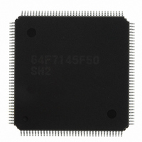
HD64F7145F50 Renesas Electronics America, HD64F7145F50 Datasheet - Page 433

HD64F7145F50
Manufacturer Part Number
HD64F7145F50
Description
IC SUPERH MCU FLASH 256K FP144F
Manufacturer
Renesas Electronics America
Series
SuperH® SH7144r
Datasheet
1.HD64F7144F50V.pdf
(932 pages)
Specifications of HD64F7145F50
Core Processor
SH-2
Core Size
32-Bit
Speed
50MHz
Connectivity
EBI/EMI, I²C, SCI
Peripherals
DMA, POR, PWM, WDT
Number Of I /o
98
Program Memory Size
256KB (256K x 8)
Program Memory Type
FLASH
Ram Size
8K x 8
Voltage - Supply (vcc/vdd)
3 V ~ 3.6 V
Data Converters
A/D 8x10b
Oscillator Type
Internal
Operating Temperature
-20°C ~ 75°C
Package / Case
144-LQFP
Lead Free Status / RoHS Status
Contains lead / RoHS non-compliant
Eeprom Size
-
Available stocks
Company
Part Number
Manufacturer
Quantity
Price
Part Number:
HD64F7145F50
Manufacturer:
RENESAS/瑞萨
Quantity:
20 000
Company:
Part Number:
HD64F7145F50V
Manufacturer:
Renesas Electronics America
Quantity:
10 000
Part Number:
HD64F7145F50V
Manufacturer:
RENESAS/瑞萨
Quantity:
20 000
- Current page: 433 of 932
- Download datasheet (6Mb)
12.4.3
The watchdog timer has a special function to clear software standby mode with an NMI interrupt
or IRQ0 to IRQ7 interrupts. When using software standby mode, set the WDT as described below.
Before Transition to Software Standby Mode: The TME bit in TCSR must be cleared to 0 to
stop the watchdog timer counter before entering software standby mode. The chip cannot enter
software standby mode while the TME bit is set to 1. Set bits CKS2 to CKS0 in TCSR so that the
counter overflow interval is equal to or longer than the oscillation settling time. See section 26.3,
AC Characteristics, for the oscillation settling time.
Recovery from Software Standby Mode: When an NMI signal or IRQ0 to IRQ7 signals are
received in software standby mode, the clock oscillator starts running and TCNT starts
incrementing at the rate selected by bits CKS2 to CKS0 before software standby mode was
entered. When TCNT overflows (changes from H'FF to H'00), the clock is presumed to be stable
and usable; clock signals are supplied to the entire chip and software standby mode ends.
For details on software standby mode, see section 24, Power-Down Modes.
12.4.4
In interval timer mode, when TCNT overflows, the OVF bit of TCSR is set to 1 and an interval
timer interrupt (ITI) is simultaneously requested. Figure 12.4 shows this timing.
Clearing Software Standby Mode
Timing of Setting Overflow Flag (OVF)
φ
TCNT
Overflow signal
(internal signal)
OVF
Figure 12.4 Timing of Setting OVF
H’FF
H’00
Rev.4.00 Mar. 27, 2008 Page 387 of 882
12. Watchdog Timer
REJ09B0108-0400
Related parts for HD64F7145F50
Image
Part Number
Description
Manufacturer
Datasheet
Request
R

Part Number:
Description:
KIT STARTER FOR M16C/29
Manufacturer:
Renesas Electronics America
Datasheet:

Part Number:
Description:
KIT STARTER FOR R8C/2D
Manufacturer:
Renesas Electronics America
Datasheet:

Part Number:
Description:
R0K33062P STARTER KIT
Manufacturer:
Renesas Electronics America
Datasheet:

Part Number:
Description:
KIT STARTER FOR R8C/23 E8A
Manufacturer:
Renesas Electronics America
Datasheet:

Part Number:
Description:
KIT STARTER FOR R8C/25
Manufacturer:
Renesas Electronics America
Datasheet:

Part Number:
Description:
KIT STARTER H8S2456 SHARPE DSPLY
Manufacturer:
Renesas Electronics America
Datasheet:

Part Number:
Description:
KIT STARTER FOR R8C38C
Manufacturer:
Renesas Electronics America
Datasheet:

Part Number:
Description:
KIT STARTER FOR R8C35C
Manufacturer:
Renesas Electronics America
Datasheet:

Part Number:
Description:
KIT STARTER FOR R8CL3AC+LCD APPS
Manufacturer:
Renesas Electronics America
Datasheet:

Part Number:
Description:
KIT STARTER FOR RX610
Manufacturer:
Renesas Electronics America
Datasheet:

Part Number:
Description:
KIT STARTER FOR R32C/118
Manufacturer:
Renesas Electronics America
Datasheet:

Part Number:
Description:
KIT DEV RSK-R8C/26-29
Manufacturer:
Renesas Electronics America
Datasheet:

Part Number:
Description:
KIT STARTER FOR SH7124
Manufacturer:
Renesas Electronics America
Datasheet:

Part Number:
Description:
KIT STARTER FOR H8SX/1622
Manufacturer:
Renesas Electronics America
Datasheet:


