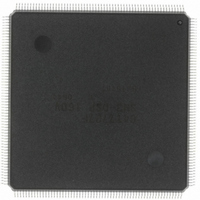
HD6417727F160CV Renesas Electronics America, HD6417727F160CV Datasheet - Page 47

HD6417727F160CV
Manufacturer Part Number
HD6417727F160CV
Description
IC SH MPU ROMLESS 240QFN
Manufacturer
Renesas Electronics America
Series
SuperH® SH7700r
Datasheet
1.HD6417727BP100CV.pdf
(1098 pages)
Specifications of HD6417727F160CV
Core Processor
SH-3 DSP
Core Size
32-Bit
Speed
160MHz
Connectivity
FIFO, SCI, SIO, SmartCard, USB
Peripherals
DMA, LCD, POR, WDT
Number Of I /o
104
Program Memory Type
ROMless
Ram Size
32K x 8
Voltage - Supply (vcc/vdd)
1.7 V ~ 2.05 V
Data Converters
A/D 6x10b; D/A 2x8b
Oscillator Type
Internal
Operating Temperature
-20°C ~ 75°C
Package / Case
240-QFP
Lead Free Status / RoHS Status
Lead free / RoHS Compliant
Eeprom Size
-
Program Memory Size
-
Available stocks
Company
Part Number
Manufacturer
Quantity
Price
Company:
Part Number:
HD6417727F160CV
Manufacturer:
RENESAS
Quantity:
37
Company:
Part Number:
HD6417727F160CV
Manufacturer:
RENESAS
Quantity:
753
- Current page: 47 of 1098
- Download datasheet (7Mb)
Figure 25.5 Power-Supply Control Sequence and States of the LCD Module .......................... 803
Figure 25.6 Power-Supply Control Sequence and States of the LCD Module .......................... 804
Figure 25.7 Power-Supply Control Sequence and States of the LCD Module .......................... 804
Figure 25.8 Clock and LCD Data Signal Example.................................................................... 809
Figure 25.9 Clock and LCD Data Signal Example.................................................................... 810
Figure 25.10 Clock and LCD Data Signal Example.................................................................... 810
Figure 25.11 Clock and LCD Data Signal Example.................................................................... 811
Figure 25.12 Clock and LCD Data Signal Example.................................................................... 811
Figure 25.13 Clock and LCD Data Signal Example.................................................................... 812
Figure 25.14 Clock and LCD Data Signal Example.................................................................... 812
Figure 25.15 Clock and LCD Data Signal Example.................................................................... 813
Figure 25.16 Clock and LCD Data Signal Example.................................................................... 813
Figure 25.17 Clock and LCD Data Signal Example.................................................................... 814
Figure 25.18 Clock and LCD Data Signal Example.................................................................... 815
Figure 25.19 Clock and LCD Data Signal Example.................................................................... 816
Figure 25.20 Clock and LCD Data Signal Example.................................................................... 817
Figure 25.21 Clock and LCD Data Signal Example.................................................................... 818
Section 26 Pin Function Controller (PFC)
Figure 26.1 Overview of the Pin Selection Function................................................................. 821
Section 28 A/D Converter
Figure 28.1 A/D Converter Block Diagram............................................................................... 858
Figure 28.2 A/D Data Register Access Operation (Reading H'AA40)...................................... 866
Figure 28.3 Example of A/D Converter Operation (Single Mode, Channel 2 Selected) ........... 868
Figure 28.4 Example of A/D Converter Operation
Figure 28.5 Example of A/D Converter Operation
Figure 28.6 A/D Conversion Timing......................................................................................... 873
Figure 28.7 External Trigger Input Timing ............................................................................... 874
Figure 28.8 Definitions of A/D Conversion Accuracy .............................................................. 876
Figure 28.9 Example of Analog Input Protection Circuit.......................................................... 877
Figure 28.10 Analog Input Pin Equivalent Circuit ...................................................................... 877
Section 29 D/A Converter
Figure 29.1 D/A Converter Block Diagram............................................................................... 879
Figure 29.2 Example of D/A Converter Operation.................................................................... 883
Section 30 PC Card Controller (PCC)
Figure 30.1 PC Card Controller Block Diagram ....................................................................... 886
(Multi Mode, Channels AN4 to AN6 Selected) ..................................................... 870
(Scan Mode, Channels AN4 to AN6 Selected) ...................................................... 872
Rev.6.00 Mar. 27, 2009 Page xlv of lvi
REJ09B0254-0600
Related parts for HD6417727F160CV
Image
Part Number
Description
Manufacturer
Datasheet
Request
R

Part Number:
Description:
KIT STARTER FOR M16C/29
Manufacturer:
Renesas Electronics America
Datasheet:

Part Number:
Description:
KIT STARTER FOR R8C/2D
Manufacturer:
Renesas Electronics America
Datasheet:

Part Number:
Description:
R0K33062P STARTER KIT
Manufacturer:
Renesas Electronics America
Datasheet:

Part Number:
Description:
KIT STARTER FOR R8C/23 E8A
Manufacturer:
Renesas Electronics America
Datasheet:

Part Number:
Description:
KIT STARTER FOR R8C/25
Manufacturer:
Renesas Electronics America
Datasheet:

Part Number:
Description:
KIT STARTER H8S2456 SHARPE DSPLY
Manufacturer:
Renesas Electronics America
Datasheet:

Part Number:
Description:
KIT STARTER FOR R8C38C
Manufacturer:
Renesas Electronics America
Datasheet:

Part Number:
Description:
KIT STARTER FOR R8C35C
Manufacturer:
Renesas Electronics America
Datasheet:

Part Number:
Description:
KIT STARTER FOR R8CL3AC+LCD APPS
Manufacturer:
Renesas Electronics America
Datasheet:

Part Number:
Description:
KIT STARTER FOR RX610
Manufacturer:
Renesas Electronics America
Datasheet:

Part Number:
Description:
KIT STARTER FOR R32C/118
Manufacturer:
Renesas Electronics America
Datasheet:

Part Number:
Description:
KIT DEV RSK-R8C/26-29
Manufacturer:
Renesas Electronics America
Datasheet:

Part Number:
Description:
KIT STARTER FOR SH7124
Manufacturer:
Renesas Electronics America
Datasheet:

Part Number:
Description:
KIT STARTER FOR H8SX/1622
Manufacturer:
Renesas Electronics America
Datasheet:

Part Number:
Description:
KIT DEV FOR SH7203
Manufacturer:
Renesas Electronics America
Datasheet:


