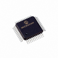
PIC16LC774/PQ Microchip Technology, PIC16LC774/PQ Datasheet - Page 115

PIC16LC774/PQ
Manufacturer Part Number
PIC16LC774/PQ
Description
IC MCU OTP 4KX14 A/D PWM 44-MQFP
Manufacturer
Microchip Technology
Series
PIC® 16Cr
Specifications of PIC16LC774/PQ
Core Processor
PIC
Core Size
8-Bit
Speed
20MHz
Connectivity
I²C, SPI, UART/USART
Peripherals
Brown-out Detect/Reset, POR, PWM, WDT
Number Of I /o
33
Program Memory Size
7KB (4K x 14)
Program Memory Type
OTP
Ram Size
256 x 8
Voltage - Supply (vcc/vdd)
2.5 V ~ 5.5 V
Data Converters
A/D 10x12b
Oscillator Type
External
Operating Temperature
0°C ~ 70°C
Package / Case
44-MQFP, 44-PQFP
Processor Series
PIC16LC
Core
PIC
Data Bus Width
8 bit
Data Ram Size
256 B
Interface Type
I2C, SPI, SSP, UART
Maximum Clock Frequency
20 MHz
Number Of Programmable I/os
33
Number Of Timers
3 bit
Operating Supply Voltage
2.5 V to 5.5 V
Maximum Operating Temperature
+ 70 C
Mounting Style
SMD/SMT
3rd Party Development Tools
52715-96, 52716-328, 52717-734
Development Tools By Supplier
ICE2000, DM163022
Minimum Operating Temperature
0 C
On-chip Adc
10 bit
Lead Free Status / RoHS Status
Lead free / RoHS Compliant
Eeprom Size
-
Lead Free Status / Rohs Status
Details
Available stocks
Company
Part Number
Manufacturer
Quantity
Price
Company:
Part Number:
PIC16LC774/PQ
Manufacturer:
Microchip Technology
Quantity:
10 000
- Current page: 115 of 201
- Download datasheet (3Mb)
10.3
This module is used to generate an interrupt when the
supply voltage falls below a specified “trip” voltage.
This module operates completely under software
FIGURE 10-3: BLOCK DIAGRAM OF LVD AND VOLTAGE REFERENCE CIRCUIT
The LVD module is enabled by setting the LVDEN bit in
the LVDCON register. The “trip point” voltage is the
minimum supply voltage level at which the device can
operate before the LVD module asserts an interrupt.
When the supply voltage is equal to or less than the trip
point, the module will generate an interrupt signal set-
ting interrupt flag bit LVDIF. If interrupt enable bit LVDIE
was set, then an interrupt is generated. The LVD inter-
rupt can wake the device from sleep. The "trip point"
voltage is software programmable to any one of 16 val-
ues, five of which are reserved (See Figure 10-1). The
trip point is selected by programming the LV3:LV0 bits
(LVDCON<3:0>).
Once the LV bits have been programmed for the speci-
fied trip voltage, the low-voltage detect circuitry is then
enabled by setting the LVDEN (LVDCON<4>) bit.
Note:
1999 Microchip Technology Inc.
V
DD
RB3/AN9/LVDIN
Low-voltage Detect (LVD)
The LVDIF bit can not be cleared until the
supply voltage rises above the LVD trip
point. If interrupts are enabled, clear the
LVDIE bit once the first LVD interrupt
occurs to prevent reentering the interrupt
service routine immediately after exiting
the ISR.
EN
V
DD
Advance Information
BODEN
BGAP
LVDEN
control. This allows a user to power the module on
and off to periodically monitor the supply voltage, and
thus minimize total current consumption.
If the bandgap reference voltage is previously unused
by either the brown-out circuitry or the voltage refer-
ence circuitry, then the bandgap circuit requires a time
to start-up and become stable before a low voltage con-
dition can be reliably detected. The low-voltage inter-
rupt flag is prevented from being set until the bandgap
has reached a stable reference voltage.
When the bandgap is stable the BGST (LVDCON<5>)
bit is set indicating that the low-voltage interrupt flag bit
is released to be set if V
LVD trip point.
10.3.1
The LVD module has an additional feature that allows
the user to supply the trip voltage to the module from
an external source.
LV3:LV0 = 1111. When these bits are set the compar-
ator input is multiplexed from an external input pin
(RB3/AN9/LVDIN.
LVDCON
EXTERNAL ANALOG VOLTAGE INPUT
LVD
VRxEN
This mode is enabled when
DD
PIC16C77X
REFCON
is equal to or less than the
A/D Ref = 2.048V
A/D Ref = 4.096V
DS30275A-page 115
Related parts for PIC16LC774/PQ
Image
Part Number
Description
Manufacturer
Datasheet
Request
R

Part Number:
Description:
3.5KB Flash, 128B RAM, 18 I/O, CLC, CWG, DDS, 10-bit ADC 20 QFN 4x4mm TUBE
Manufacturer:
Microchip Technology
Datasheet:

Part Number:
Description:
3.5KB Flash, 128B RAM, 18 I/O, CLC, CWG, DDS, 10-bit ADC 20 PDIP .300in TUBE
Manufacturer:
Microchip Technology
Datasheet:

Part Number:
Description:
3.5KB Flash, 128B RAM, 18 I/O, CLC, CWG, DDS, 10-bit ADC 20 SOIC .300in TUBE
Manufacturer:
Microchip Technology
Datasheet:

Part Number:
Description:
3.5KB Flash, 128B RAM, 18 I/O, CLC, CWG, DDS, 10-bit ADC 20 SSOP .209in TUBE
Manufacturer:
Microchip Technology
Datasheet:

Part Number:
Description:
3.5KB Flash, 128B RAM, 18 I/O, CLC, CWG, DDS, 10-bit ADC 20 QFN 4x4mm TUBE
Manufacturer:
Microchip Technology
Datasheet:

Part Number:
Description:
3.5KB Flash, 128B RAM, 18 I/O, CLC, CWG, DDS, 10-bit ADC 20 PDIP .300in TUBE
Manufacturer:
Microchip Technology
Datasheet:

Part Number:
Description:
3.5KB Flash, 128B RAM, 18 I/O, CLC, CWG, DDS, 10-bit ADC 20 SOIC .300in TUBE
Manufacturer:
Microchip Technology
Datasheet:

Part Number:
Description:
3.5KB Flash, 128B RAM, 18 I/O, CLC, CWG, DDS, 10-bit ADC 20 SSOP .209in TUBE
Manufacturer:
Microchip Technology
Datasheet:

Part Number:
Description:
3.5KB Flash, 128B RAM, 18 I/O, CLC, CWG, DDS, 10-bit ADC 20 QFN 4x4mm T/R
Manufacturer:
Microchip Technology
Datasheet:

Part Number:
Description:
3.5KB Flash, 128B RAM, 18 I/O, CLC, CWG, DDS, 10-bit ADC 20 SOIC .300in T/R
Manufacturer:
Microchip Technology
Datasheet:

Part Number:
Description:
3.5KB Flash, 128B RAM, 18 I/O, CLC, CWG, DDS, 10-bit ADC 20 SSOP .209in T/R
Manufacturer:
Microchip Technology
Datasheet:

Part Number:
Description:
3.5KB Flash, 128B RAM, 18 I/O, CLC, CWG, DDS, 10-bit ADC 20 QFN 4x4mm TUBE
Manufacturer:
Microchip Technology
Datasheet:

Part Number:
Description:
3.5KB Flash, 128B RAM, 18 I/O, CLC, CWG, DDS, 10-bit ADC 20 PDIP .300in TUBE
Manufacturer:
Microchip Technology
Datasheet:

Part Number:
Description:
3.5KB Flash, 128B RAM, 18 I/O, CLC, CWG, DDS, 10-bit ADC 20 SOIC .300in TUBE
Manufacturer:
Microchip Technology
Datasheet:

Part Number:
Description:
3.5KB Flash, 128B RAM, 18 I/O, CLC, CWG, DDS, 10-bit ADC 20 SSOP .209in TUBE
Manufacturer:
Microchip Technology
Datasheet:


