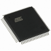
AT80C51SND1C-ROTIL Atmel, AT80C51SND1C-ROTIL Datasheet - Page 140

AT80C51SND1C-ROTIL
Manufacturer Part Number
AT80C51SND1C-ROTIL
Description
IC MCU FLASH MP3 DECODER 80-TQFP
Manufacturer
Atmel
Series
80Cr
Datasheet
1.AT80C51SND1C-ROTIL.pdf
(213 pages)
Specifications of AT80C51SND1C-ROTIL
Core Processor
8051
Core Size
8-Bit
Speed
40MHz
Connectivity
I²C, IDE/ATAPI, MMC, SPI, UART/USART, USB
Peripherals
Audio, I²S, MP3, PCM, POR, WDT
Number Of I /o
44
Program Memory Type
ROMless
Ram Size
2.25K x 8
Voltage - Supply (vcc/vdd)
2.7 V ~ 3.3 V
Data Converters
A/D 2x10b
Oscillator Type
Internal
Operating Temperature
-40°C ~ 85°C
Package / Case
80-TQFP, 80-VQFP
Lead Free Status / RoHS Status
Contains lead / RoHS non-compliant
Eeprom Size
-
Program Memory Size
-
Other names
AT80C51SND1CROTIL
Available stocks
Company
Part Number
Manufacturer
Quantity
Price
- Current page: 140 of 213
- Download datasheet (3Mb)
Notes:
18.4.5
18.5
140
Baud Rate
9600
4800
1. These frequencies are achieved in X1 mode, F
2. These frequencies are achieved in X2 mode, F
Multiprocessor Communication (Modes 2 and 3)
AT8xC51SND1C
Baud Rate Selection (Mode 2)
SPD
1
1
SMOD1
F
PER
1
1
In mode 2, the baud rate can only be programmed to 2 fixed values: 1/16 or 1/32 of the periph-
eral clock frequency.
As shown in Figure 18-14 the selection is done using SMOD1 bit in PCON register.
Figure 18-15 gives the baud rate calculation formula depending on the selection.
Figure 18-14. Baud Rate Generator Selection (Mode 2)
Figure 18-15. Baud Rate Formula (Mode 2)
Modes 2 and 3 provide a ninth-bit mode to facilitate multiprocessor communication. To enable
this feature, set SM2 bit in SCON register. When the multiprocessor communication feature is
enabled, the serial Port can differentiate between data frames (ninth bit clear) and address
frames (ninth bit set). This allows the AT8xC51SND1C to function as a slave processor in an
environment where multiple slave processors share a single serial line.
When the multiprocessor communication feature is enabled, the receiver ignores frames with
the ninth bit clear. The receiver examines frames with the ninth bit set for an address match. If
the received address matches the slaves address, the receiver hardware sets RB8 and RI bits in
SCON register, generating an interrupt.
The addressed slave’s software then clears SM2 bit in SCON register and prepares to receive
the data Bytes. The other slaves are unaffected by these data Bytes because they are waiting to
respond to their own addresses.
= 12 MHz
BRL
178
100
(2)
Error %
CLOCK
PER
0.16
0.16
SPD
1
1
PER
PER
= F
= F
SMOD1
OSC
OSC
F
Baud_Rate=
PER
÷ 2
1
1
.
÷ 2.
= 16 MHz
SMOD1
BRL
PCON.7
152
48
(2)
0
1
2
SMOD1
Error %
32
0.16
0.16
⋅ F
÷ 16
PER
SPD
1
1
To Serial Port
SMOD1
F
PER
1
0
= 20 MHz
BRL
126
126
4109L–8051–02/08
(2)
Error %
0.16
0.16
Related parts for AT80C51SND1C-ROTIL
Image
Part Number
Description
Manufacturer
Datasheet
Request
R

Part Number:
Description:
DEV KIT FOR AVR/AVR32
Manufacturer:
Atmel
Datasheet:

Part Number:
Description:
INTERVAL AND WIPE/WASH WIPER CONTROL IC WITH DELAY
Manufacturer:
ATMEL Corporation
Datasheet:

Part Number:
Description:
Low-Voltage Voice-Switched IC for Hands-Free Operation
Manufacturer:
ATMEL Corporation
Datasheet:

Part Number:
Description:
MONOLITHIC INTEGRATED FEATUREPHONE CIRCUIT
Manufacturer:
ATMEL Corporation
Datasheet:

Part Number:
Description:
AM-FM Receiver IC U4255BM-M
Manufacturer:
ATMEL Corporation
Datasheet:

Part Number:
Description:
Monolithic Integrated Feature Phone Circuit
Manufacturer:
ATMEL Corporation
Datasheet:

Part Number:
Description:
Multistandard Video-IF and Quasi Parallel Sound Processing
Manufacturer:
ATMEL Corporation
Datasheet:

Part Number:
Description:
High-performance EE PLD
Manufacturer:
ATMEL Corporation
Datasheet:

Part Number:
Description:
8-bit Flash Microcontroller
Manufacturer:
ATMEL Corporation
Datasheet:

Part Number:
Description:
2-Wire Serial EEPROM
Manufacturer:
ATMEL Corporation
Datasheet:


