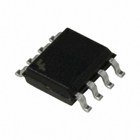
ACE1202LEM8X Fairchild Semiconductor, ACE1202LEM8X Datasheet - Page 23

ACE1202LEM8X
Manufacturer Part Number
ACE1202LEM8X
Description
IC MCU 2KBIT EEPROM 8SOIC
Manufacturer
Fairchild Semiconductor
Series
ACEX® 12xxr
Datasheet
1.ACE1202EMX.pdf
(39 pages)
Specifications of ACE1202LEM8X
Core Processor
ACE1202
Core Size
8-Bit
Speed
4MHz
Peripherals
Brown-out Detect/Reset, LVD, POR, PWM, WDT
Number Of I /o
6
Program Memory Size
2KB (2K x 8)
Program Memory Type
EEPROM
Eeprom Size
64 x 8
Ram Size
64 x 8
Voltage - Supply (vcc/vdd)
1.8 V ~ 5.5 V
Oscillator Type
Internal
Operating Temperature
-40°C ~ 85°C
Package / Case
8-SOIC (3.9mm Width)
Lead Free Status / RoHS Status
Lead free / RoHS Compliant
Data Converters
-
Connectivity
-
ACE1202 Product Family Rev. B.1
The Difference Input Capture mode works similarly to the stan-
dard Input Capture mode. However, for the Difference Input
Capture the timer automatically captures the elapsed time be-
tween the selected edges without the core needing to perform the
calculation.
For example, the standard Input Captrue mode requires that the
timer be configured to capture a particular edge (rising or falling)
at which time the timer's value is copied into the capture register.
if the elapsed time is required, software must move the captured
data into RAM and reconfigure the Input Capture mode to capture
on the next edge (rising or falling). Software must then subtract the
difference between the two edges to yield useful information.
The Difference Capture mode eliminates the need for software
intervention and allows for capturing very short pulse or cycle
widths. it can be configured to capture the elapsed time between:
1. positive to negative-going edges
2. positive to positive-going edges
3. negative to positive-going edges
4. negative to negative-going edges
Underflow
Interrupt
Interrupt
Capture
T1
Edge Selector
Logic
Instruction
Clock
16-bit Timer (TMR1)
Once configured, the Difference Capture timer waits for the first
selected edge. when the edge transition has occurred, the 16-bit
timer starts counting up based every instruction clock cycle. It will
continue to count until the second selected edge transition occurs
at which time the timer stops and stores the elapse time into the
T1RA register.
Software can now read the differnce between transitions directly
without using any processor resources. However, like the stan-
dard Input Capture mode both the capture (T1PND) and the
underflow (T1C0) flags must be monitored and handled appropri-
ately. This feature allows the ACEx microcontroller to capture very
small pulses where standard microcontrollers might have missed
cycles due to the limited bandwidth.
16-bit Input Capture
Register (T1RA)
Difference
Logic
Data
Bus
www.fairchildsemi.com


