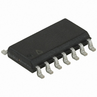
ATTINY44-20SSU Atmel, ATTINY44-20SSU Datasheet - Page 29

ATTINY44-20SSU
Manufacturer Part Number
ATTINY44-20SSU
Description
IC MCU AVR 4K FLASH 20MHZ 14SOIC
Manufacturer
Atmel
Series
AVR® ATtinyr
Specifications of ATTINY44-20SSU
Core Processor
AVR
Core Size
8-Bit
Speed
20MHz
Connectivity
USI
Peripherals
Brown-out Detect/Reset, POR, PWM, WDT
Number Of I /o
12
Program Memory Size
4KB (2K x 16)
Program Memory Type
FLASH
Eeprom Size
256 x 8
Ram Size
256 x 8
Voltage - Supply (vcc/vdd)
2.7 V ~ 5.5 V
Data Converters
A/D 8x10b
Oscillator Type
Internal
Operating Temperature
-40°C ~ 85°C
Package / Case
14-SOIC (3.9mm Width), 14-SOL
Cpu Family
ATtiny
Device Core
AVR
Device Core Size
8b
Frequency (max)
20MHz
Interface Type
SPI/USI
Total Internal Ram Size
256Byte
# I/os (max)
12
Number Of Timers - General Purpose
2
Operating Supply Voltage (typ)
3.3/5V
Operating Supply Voltage (max)
5.5V
Operating Supply Voltage (min)
2.7V
On-chip Adc
8-chx10-bit
Instruction Set Architecture
RISC
Operating Temp Range
-40C to 85C
Operating Temperature Classification
Industrial
Mounting
Surface Mount
Pin Count
14
Package Type
SOIC
For Use With
ATAVRISP2 - PROGRAMMER AVR IN SYSTEM
Lead Free Status / RoHS Status
Lead free / RoHS Compliant
- Current page: 29 of 238
- Download datasheet (5Mb)
8006K–AVR–10/10
Table 6-9.
Notes:
The Oscillator can operate in three different modes, each optimized for a specific frequency
range. The operating mode is selected by fuses CKSEL3:1 as shown in
The CKSEL0 Fuse together with the SUT1:0 Fuses select the start-up times as shown in
6-10.
Table 6-10.
Notes:
CKSEL0
CKSEL3:1
100
0
0
0
0
1
1
1
1
101
110
111
(1)
1. This option should not be used with crystals, only with ceramic resonators.
1. When the BOD has been disabled by software, the wake-up time from sleep mode will be
2. These options should only be used when not operating close to the maximum frequency of the
3. These options are intended for use with ceramic resonators and will ensure frequency stability
approximately 60µs to ensure that the BOD is working correctly before the MCU continues
executing code.
device, and only if frequency stability at start-up is not important for the application. These
options are not suitable for crystals.
at start-up. They can also be used with crystals when not operating close to the maximum fre-
quency of the device, and if frequency stability at start-up is not important for the application.
SUT1:0
Crystal Oscillator Operating Modes
Start-up Times for the Crystal Oscillator Clock Selection
00
01
10
11
00
01
10
11
Frequency Range (MHz)
Start-up Time from
0.4 - 0.9
0.9 - 3.0
3.0 - 8.0
Power-down
8.0 -
258 CK
258 CK
1K CK
1K CK
1K CK
16K CK
16K CK
16K CK
(3)
(3)
(3)
(2)
(2)
(1)
Additional Delay
14CK + 64 ms
14CK + 64 ms
14CK + 64 ms
14CK + 4 ms
14CK + 4 ms
14CK + 4 ms
from Reset
Recommended C1 and C2 Value (pF)
14CK
14CK
ATtiny24/44/84
12 - 22
12 - 22
12 - 22
Recommended Usage
Ceramic resonator,
fast rising power
Ceramic resonator,
slowly rising power
Ceramic resonator,
BOD enabled
Ceramic resonator,
fast rising power
Ceramic resonator,
slowly rising power
Crystal Oscillator,
BOD enabled
Crystal Oscillator,
fast rising power
Crystal Oscillator,
slowly rising power
–
Table
6-9.
Table
29
Related parts for ATTINY44-20SSU
Image
Part Number
Description
Manufacturer
Datasheet
Request
R

Part Number:
Description:
Manufacturer:
Atmel Corporation
Datasheet:

Part Number:
Description:
Manufacturer:
Atmel Corporation
Datasheet:

Part Number:
Description:
MCU AVR 4K FLASH 15MHZ 20-QFN
Manufacturer:
Atmel
Datasheet:

Part Number:
Description:
IC MCU AVR 4K FLASH 20MHZ 20-QFN
Manufacturer:
Atmel
Datasheet:

Part Number:
Description:
MCU AVR 4KB FLASH 20MHZ 14SOIC
Manufacturer:
Atmel
Datasheet:

Part Number:
Description:
MCU AVR 4KB FLASH 20MHZ 20QFN
Manufacturer:
Atmel
Datasheet:

Part Number:
Description:
IC MCU AVR 4K FLASH 15MHZ 14SOIC
Manufacturer:
Atmel
Datasheet:

Part Number:
Description:
IC MCU AVR 4K FLASH 20MHZ 14-DIP
Manufacturer:
Atmel
Datasheet:

Part Number:
Description:
IC, MCU, 8BIT, 2K FLASH, 20SOIC
Manufacturer:
Atmel
Datasheet:

Part Number:
Description:
IC, MCU, 8BIT, 2K FLASH, 20PDIP
Manufacturer:
Atmel
Datasheet:

Part Number:
Description:
IC, MCU, 8BIT, 8K FLASH, 20PDIP
Manufacturer:
Atmel
Datasheet:

Part Number:
Description:
IC, MCU, 8BIT, 8K FLASH, 20SOIC
Manufacturer:
Atmel
Datasheet:

Part Number:
Description:
DEV KIT FOR AVR/AVR32
Manufacturer:
Atmel
Datasheet:


