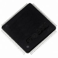
ST92F250CV2TB STMicroelectronics, ST92F250CV2TB Datasheet - Page 235

ST92F250CV2TB
Manufacturer Part Number
ST92F250CV2TB
Description
IC MCU 256K FLASH 100-TQFP
Manufacturer
STMicroelectronics
Series
ST9r
Datasheet
1.ST92F150CV1TB.pdf
(429 pages)
Specifications of ST92F250CV2TB
Core Processor
ST9
Core Size
8/16-Bit
Speed
24MHz
Connectivity
CAN, I²C, LIN, SCI, SPI
Peripherals
DMA, LVD, POR, PWM, WDT
Number Of I /o
80
Program Memory Size
256KB (256K x 8)
Program Memory Type
FLASH
Eeprom Size
1K x 8
Ram Size
8K x 8
Voltage - Supply (vcc/vdd)
4.5 V ~ 5.5 V
Data Converters
A/D 16x10b
Oscillator Type
Internal
Operating Temperature
-40°C ~ 105°C
Package / Case
100-TQFP, 100-VQFP
Processor Series
ST92F25x
Core
ST9
Data Bus Width
8 bit, 16 bit
Data Ram Size
8 KB
Interface Type
CAN, I2C, SCI, SPI
Maximum Clock Frequency
24 MHz
Number Of Programmable I/os
80
Number Of Timers
5 x 16 bit
Operating Supply Voltage
4.5 V to 5.5 V
Maximum Operating Temperature
+ 105 C
Mounting Style
SMD/SMT
Development Tools By Supplier
ST92F150-EPB
Minimum Operating Temperature
- 40 C
On-chip Adc
16 bit x 10 bit
Lead Free Status / RoHS Status
Lead free / RoHS Compliant
Other names
497-2140
Available stocks
Company
Part Number
Manufacturer
Quantity
Price
- Current page: 235 of 429
- Download datasheet (8Mb)
MULTIPROTOCOL SERIAL COMMUNICATIONS INTERFACE (Cont’d)
BAUD RATE GENERATOR HIGH REGISTER
(BRGHR)
R252 - Read/Write
Reset value: undefined
BAUD RATE GENERATOR LOW REGISTER
(BRGLR)
R253 - Read/Write
Reset value: undefined
Bit 15:0 = Baud Rate Generator MSB and LSB.
The Baud Rate generator is a programmable di-
vide by “N” counter which can be used to generate
the clocks for the transmitter and/or receiver. This
counter divides the clock input by the value in the
Baud Rate Generator Register. The minimum
baud rate divisor is 2 and the maximum divisor is
2
tor, the divisor value is immediately loaded into the
counter. This prevents potentially long random
counts on the initial load. If set to 0 or 1, the Baud
Rate Generator is stopped.
SYNCHRONOUS INPUT CONTROL (SICR)
R254 - Read/Write
Reset value: 0000 0011 (03h)
Bit 7 = SMEN: Synchronous Mode Enable.
0: Disable all features relating to Synchronous
1: Select Synchronous mode with its programmed
SMEN
BG15
16
BG7
mode (the contents of SICR and SOCR are ig-
nored).
I/O configuration.
15
7
7
-1. After initialization of the baud rate genera-
INPL XCKPL DCDEN DCDPL INPEN
BG14
BG6
BG5
BG13
BG4
BG12
MULTIPROTOCOL SERIAL COMMUNICATIONS INTERFACE (SCI-M)
BG3
BG11
BG2
BG10
BG1
BG9
X
BG0
BG8
0
X
8
0
Bit 6 = INPL: SIN Input Polarity.
0: Polarity not inverted.
1: Polarity inverted.
Note: INPL only affects received data. In Auto-
Echo mode SOUT = SIN even if INPL is set. In
Loop-Back mode the state of the INPL bit is irrele-
vant.
Bit 5 = XCKPL: Receiver Clock Polarity.
0: RXCLK is active on the rising edge.
1: RXCLK is active on the falling edge.
Note: XCKPL only affects the receiver clock. In
Auto-Echo mode CLKOUT = RXCLK independ-
ently of the XCKPL status. In Loop-Back the state
of the XCKPL bit is irrelevant.
Bit 4 = DCDEN: DCD Input Enable.
0: Disable hardware synchronization.
1: Enable hardware synchronization.
Note: When DCDEN is set, RXCLK drives the re-
ceiver section only during the active level of the
DCD input (DCD works as a gate on RXCLK, in-
forming the MCU that a transmitting device is
sending a synchronous frame to it).
Bit 3 = DCDPL: DCD Input Polarity.
0: The DCD input is active when LOW.
1: The DCD input is active when HIGH.
Note: DCDPL only affects the gating activity of the
receiver clock. In Auto-Echo mode RTS = DCD in-
dependently of DCDPL. In Loop-Back mode, the
state of DCDPL is irrelevant.
Bit 2 = INPEN: All Input Disable.
0: Enable SIN/RXCLK/DCD inputs.
1: Disable SIN/RXCLK/DCD inputs.
Bit 1:0 = “Don't Care”
235/429
9
Related parts for ST92F250CV2TB
Image
Part Number
Description
Manufacturer
Datasheet
Request
R

Part Number:
Description:
STMicroelectronics [RIPPLE-CARRY BINARY COUNTER/DIVIDERS]
Manufacturer:
STMicroelectronics
Datasheet:

Part Number:
Description:
STMicroelectronics [LIQUID-CRYSTAL DISPLAY DRIVERS]
Manufacturer:
STMicroelectronics
Datasheet:

Part Number:
Description:
BOARD EVAL FOR MEMS SENSORS
Manufacturer:
STMicroelectronics
Datasheet:

Part Number:
Description:
NPN TRANSISTOR POWER MODULE
Manufacturer:
STMicroelectronics
Datasheet:

Part Number:
Description:
TURBOSWITCH ULTRA-FAST HIGH VOLTAGE DIODE
Manufacturer:
STMicroelectronics
Datasheet:

Part Number:
Description:
Manufacturer:
STMicroelectronics
Datasheet:

Part Number:
Description:
DIODE / SCR MODULE
Manufacturer:
STMicroelectronics
Datasheet:

Part Number:
Description:
DIODE / SCR MODULE
Manufacturer:
STMicroelectronics
Datasheet:

Part Number:
Description:
Search -----> STE16N100
Manufacturer:
STMicroelectronics
Datasheet:

Part Number:
Description:
Search ---> STE53NA50
Manufacturer:
STMicroelectronics
Datasheet:

Part Number:
Description:
NPN Transistor Power Module
Manufacturer:
STMicroelectronics
Datasheet:

Part Number:
Description:
DIODE / SCR MODULE
Manufacturer:
STMicroelectronics
Datasheet:


