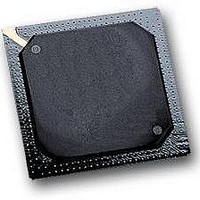
MPC564CVR40 Freescale Semiconductor, MPC564CVR40 Datasheet - Page 63

MPC564CVR40
Manufacturer Part Number
MPC564CVR40
Description
IC MPU 32BIT W/CODE COMP 388PBGA
Manufacturer
Freescale Semiconductor
Series
MPC5xxr
Specifications of MPC564CVR40
Core Processor
PowerPC
Core Size
32-Bit
Speed
40MHz
Connectivity
CAN, EBI/EMI, SCI, SPI, UART/USART
Peripherals
POR, PWM, WDT
Number Of I /o
56
Program Memory Size
512KB (512K x 8)
Program Memory Type
FLASH
Ram Size
32K x 8
Voltage - Supply (vcc/vdd)
2.5 V ~ 2.7 V
Data Converters
A/D 32x10b
Oscillator Type
External
Operating Temperature
-40°C ~ 85°C
Package / Case
388-BGA
Processor Series
MPC5xx
Core
PowerPC
Data Bus Width
32 bit
Data Ram Size
32 KB
Interface Type
CAN, JTAG, QSPI, SCI, SPI, UART
Maximum Clock Frequency
40 MHz
Number Of Programmable I/os
56
Number Of Timers
2
Maximum Operating Temperature
+ 85 C
Mounting Style
SMD/SMT
Minimum Operating Temperature
- 40 C
On-chip Adc
2 (10 bit, 32 Channel)
For Use With
MPC564EVB - KIT EVAL FOR MPC561/562/563/564
Lead Free Status / RoHS Status
Lead free / RoHS Compliant
Eeprom Size
-
Lead Free Status / Rohs Status
Details
Available stocks
Company
Part Number
Manufacturer
Quantity
Price
Company:
Part Number:
MPC564CVR40
Manufacturer:
Freescale Semiconductor
Quantity:
10 000
- Current page: 63 of 1420
- Download datasheet (11Mb)
Table
Number
i
ii
1-1
1-2
2-1
2-2
2-3
2-4
2-5
2-6
2-7
2-8
2-9
2-10
2-11
2-12
2-13
2-14
3-1
3-2
3-3
3-4
3-5
3-6
3-7
3-8
3-9
3-10
3-11
3-12
3-13
3-14
3-15
3-16
3-17
3-18
3-19
3-20
3-21
Freescale Semiconductor
Notational Conventions ..................................................................................................... 1-lxxxii
Acronyms and Abbreviated Terms .................................................................................... 1-lxxxii
MPC56x Family Features ......................................................................................................... 1-1
Differences Between MPC555 and MPC561/MPC563............................................................ 1-9
MPC561/MPC563 Signal Descriptions .................................................................................... 2-3
MPC561/MPC563 Signal Sharing.......................................................................................... 2-20
Reduced and Full Port Mode Pads.......................................................................................... 2-21
Full Port Only Mode Pads ...................................................................................................... 2-21
PDMCR Field Descriptions .................................................................................................... 2-22
PDMCR2 Field Description.................................................................................................... 2-24
TCNC Pad Functionalities ...................................................................................................... 2-25
PPMPAD Pad Functionalities................................................................................................. 2-25
Enhanced PCS 4 & 5 Pad Function ........................................................................................ 2-26
Enhanced PCS 6 & 7 Pad Function ........................................................................................ 2-28
MPC561/MPC563 Development Support Shared Signals ..................................................... 2-28
MPC561/MPC563 Signal Reset State .................................................................................... 2-34
RCPU Execution Units ............................................................................................................. 3-4
Supervisor-Level SPRs ............................................................................................................. 3-9
Development Support SPRs.................................................................................................... 3-11
FPSCR Bit Categories ............................................................................................................ 3-13
FPSCR Bit Descriptions ......................................................................................................... 3-14
Floating-Point Result Flags in FPSCR ................................................................................... 3-16
Bit Settings for CR0 Field of CR............................................................................................ 3-17
Bit Settings for CR1 Field of CR............................................................................................ 3-17
CRn Field Bit Settings for Compare Instructions ................................................................... 3-18
Integer Exception Register Bit Descriptions .......................................................................... 3-18
Machine State Register Bit Descriptions ................................................................................ 3-20
Floating-Point Exception Mode Bits ...................................................................................... 3-22
Uses of SPRG0–SPRG3 ......................................................................................................... 3-24
Processor Version Register Bit Descriptions.......................................................................... 3-25
EIE, EID, AND NRI Registers ............................................................................................... 3-25
FPECR Bit Descriptions ......................................................................................................... 3-26
Instruction Set Summary ........................................................................................................ 3-28
RCPU Exception Classes........................................................................................................ 3-35
Instruction Latency and Blockage .......................................................................................... 3-39
Floating-Point Exception Mode Encoding ............................................................................. 3-44
Enhanced PCS Functionality ................................................................................................. 2-25
MPC561/MPC563 Mode Selection Options.......................................................................... 2-29
Exception Vector Offset Table .............................................................................................. 3-36
MPC561/MPC563 Reference Manual, Rev. 1.2
Tables
Title
Number
Page
lxiii
Related parts for MPC564CVR40
Image
Part Number
Description
Manufacturer
Datasheet
Request
R

Part Number:
Description:
MPC5 1K0 5%
Manufacturer:
TE Connectivity
Datasheet:

Part Number:
Description:
MPC5 500R 5%
Manufacturer:
TE Connectivity
Datasheet:

Part Number:
Description:
MPC5 5K0 5%
Manufacturer:
Tyco Electronics
Datasheet:

Part Number:
Description:
MPC5 5R0 5%
Manufacturer:
Tyco Electronics
Datasheet:

Part Number:
Description:
MPC5 50K 5%
Manufacturer:
Tyco Electronics
Datasheet:

Part Number:
Description:
MPC5 1R0 5%
Manufacturer:
Tyco Electronics
Datasheet:
Part Number:
Description:
Manufacturer:
Freescale Semiconductor, Inc
Datasheet:
Part Number:
Description:
Manufacturer:
Freescale Semiconductor, Inc
Datasheet:
Part Number:
Description:
Manufacturer:
Freescale Semiconductor, Inc
Datasheet:
Part Number:
Description:
Manufacturer:
Freescale Semiconductor, Inc
Datasheet:
Part Number:
Description:
Manufacturer:
Freescale Semiconductor, Inc
Datasheet:


