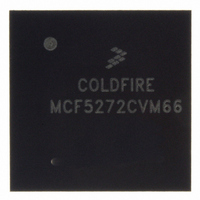
MCF5272CVM66 Freescale Semiconductor, MCF5272CVM66 Datasheet - Page 331

MCF5272CVM66
Manufacturer Part Number
MCF5272CVM66
Description
IC MPU 66MHZ COLDFIRE 196-MAPBGA
Manufacturer
Freescale Semiconductor
Series
MCF527xr
Specifications of MCF5272CVM66
Core Processor
Coldfire V2
Core Size
32-Bit
Speed
66MHz
Connectivity
EBI/EMI, Ethernet, I²C, SPI, UART/USART, USB
Peripherals
DMA, WDT
Number Of I /o
32
Program Memory Size
16KB (4K x 32)
Program Memory Type
ROM
Ram Size
1K x 32
Voltage - Supply (vcc/vdd)
3 V ~ 3.6 V
Oscillator Type
External
Operating Temperature
-40°C ~ 85°C
Package / Case
196-MAPBGA
Cpu Speed
66MHz
Embedded Interface Type
UART, QSPI, USB, TDM
Digital Ic Case Style
BGA
No. Of Pins
196
Supply Voltage Range
3V To 3.6V
Rohs Compliant
Yes
Family Name
MCF5xxx
Device Core
ColdFire
Device Core Size
32b
Frequency (max)
66MHz
Instruction Set Architecture
RISC
Supply Voltage 1 (typ)
3.3V
Operating Temp Range
-40C to 85C
Operating Temperature Classification
Industrial
Mounting
Surface Mount
Pin Count
196
Package Type
MA-BGA
Lead Free Status / RoHS Status
Lead free / RoHS Compliant
Eeprom Size
-
Data Converters
-
Lead Free Status / Rohs Status
Compliant
Available stocks
Company
Part Number
Manufacturer
Quantity
Price
Company:
Part Number:
MCF5272CVM66
Manufacturer:
MOT
Quantity:
3
Company:
Part Number:
MCF5272CVM66
Manufacturer:
Freescale Semiconductor
Quantity:
10 000
Part Number:
MCF5272CVM66
Manufacturer:
FREESCALE
Quantity:
20 000
Company:
Part Number:
MCF5272CVM66J
Manufacturer:
NSC
Quantity:
36
Company:
Part Number:
MCF5272CVM66J
Manufacturer:
Freescale Semiconductor
Quantity:
10 000
- Current page: 331 of 544
- Download datasheet (7Mb)
13.6
This section provides examples for applications.
13.6.1
The following section describes the initialization of the PLIC ports and gives three application examples
demonstrating the connection of multiple transceivers or CODECs to the PLIC module.
13.6.2
The ports on the PLIC module of the MCF5272 require a number of registers to be configured after
power-on reset and prior to use. The following are the steps necessary for initializing the ports.
The port configuration registers, PnCR, and the interrupt configuration register, PnICR, must be initialized
before using any port.
13.6.2.1
The following example shows a basic configuration of port 1, assuming the following:
Freescale Semiconductor
•
•
•
•
•
•
•
•
•
•
•
•
•
Specify which ports are active.
Specify the operational modes, IDL8, IDL10, and so on, for the active ports, PnCR[M].
If GCI mode is specified in PnCR[M], select whether GCI SCIT mode is to be used, PnCR[G/S]
If port 1 is used, program whether the 2-KHz frame interrupt is to be derived from port 0 or port 1,
PnCR[FSM].
If port 1 is used, program whether it receives as inputs DCL and FSC or whether it drives these
signals as outputs.
If the port is in GCI mode, the PnCR[ACT] bit may be set if GCI Activation should be requested.
If port 3 is used, program the PnCR[DMX] bit if this port is routed through physical interface 3
(DIN3/DOUT3).
Program the shift direction for the B1 and B2 channels, PnCR[SHB1–SHB2], to specify msb or lsb
first.
Program PnCR[ENB1–ENB2] to specify whether B1 or B2 is enabled at initialization.
Port 1 is active as slave using IDL10 mode
2-KHz frame interrupt derived from port 1
msb first on B1 and B2
B1 and B2 disabled.
Application Examples
Introduction
PLIC Initialization
Port Configuration Example
MCF5272 ColdFire
®
Integrated Microprocessor User’s Manual, Rev. 3
Physical Layer Interface Controller (PLIC)
13-35
Related parts for MCF5272CVM66
Image
Part Number
Description
Manufacturer
Datasheet
Request
R
Part Number:
Description:
Mcf5272 Coldfire Integrated Microprocessor User
Manufacturer:
Freescale Semiconductor, Inc
Datasheet:

Part Number:
Description:
MCF5272 Interrupt Service Routine for the Physical Layer Interface Controller
Manufacturer:
Freescale Semiconductor / Motorola
Datasheet:
Part Number:
Description:
Manufacturer:
Freescale Semiconductor, Inc
Datasheet:
Part Number:
Description:
Manufacturer:
Freescale Semiconductor, Inc
Datasheet:
Part Number:
Description:
Manufacturer:
Freescale Semiconductor, Inc
Datasheet:
Part Number:
Description:
Manufacturer:
Freescale Semiconductor, Inc
Datasheet:
Part Number:
Description:
Manufacturer:
Freescale Semiconductor, Inc
Datasheet:
Part Number:
Description:
Manufacturer:
Freescale Semiconductor, Inc
Datasheet:
Part Number:
Description:
Manufacturer:
Freescale Semiconductor, Inc
Datasheet:
Part Number:
Description:
Manufacturer:
Freescale Semiconductor, Inc
Datasheet:
Part Number:
Description:
Manufacturer:
Freescale Semiconductor, Inc
Datasheet:
Part Number:
Description:
Manufacturer:
Freescale Semiconductor, Inc
Datasheet:
Part Number:
Description:
Manufacturer:
Freescale Semiconductor, Inc
Datasheet:
Part Number:
Description:
Manufacturer:
Freescale Semiconductor, Inc
Datasheet:
Part Number:
Description:
Manufacturer:
Freescale Semiconductor, Inc
Datasheet:


