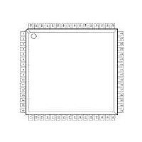
XR16C854IV-F Exar Corporation, XR16C854IV-F Datasheet - Page 35

XR16C854IV-F
Manufacturer Part Number
XR16C854IV-F
Description
IC UART FIFO 128B QUAD 64LQFP
Manufacturer
Exar Corporation
Type
Quad UART with 128-byte FIFOsr
Datasheet
1.XR16C854IV-F.pdf
(54 pages)
Specifications of XR16C854IV-F
Number Of Channels
4, QUART
Package / Case
64-LQFP
Features
*
Fifo's
128 Byte
Protocol
RS232, RS485
Voltage - Supply
2.97 V ~ 5.5 V
With Auto Flow Control
Yes
With Irda Encoder/decoder
Yes
With False Start Bit Detection
Yes
With Modem Control
Yes
With Cmos
Yes
Mounting Type
Surface Mount
Data Rate
2 Mbps
Supply Voltage (max)
5.5 V
Supply Voltage (min)
2.97 V
Supply Current
3 mA to 6 mA
Maximum Operating Temperature
+ 85 C
Minimum Operating Temperature
- 45 C
Mounting Style
SMD/SMT
Operating Supply Voltage
2.97 V to 5.5 V
No. Of Channels
4
Uart Features
Tx/Rx FIFO Counters
Supply Voltage Range
2.97V To 5.5V
Operating Temperature Range
-40°C To +85°C
Digital Ic Case Style
LQFP
Rohs Compliant
Yes
Lead Free Status / RoHS Status
Lead free / RoHS Compliant
Lead Free Status / RoHS Status
Lead free / RoHS Compliant, Lead free / RoHS Compliant
Other names
1016-1276
Available stocks
Company
Part Number
Manufacturer
Quantity
Price
Company:
Part Number:
XR16C854IV-F
Manufacturer:
HYNIX
Quantity:
101
Company:
Part Number:
XR16C854IV-F
Manufacturer:
Exar Corporation
Quantity:
10 000
xr
REV. 3.0.1
MSR[7]: CD Input Status
CD# (active high, logical 1). Normally this bit is the compliment of the CD# input. In the loopback mode this bit
is equivalent to bit-3 in the MCR register. The CD# input may be used as a general purpose input when the
modem interface is not used.
This is a 8-bit general purpose register for the user to store temporary data. The content of this register is
preserved during sleep mode but becomes 0xFF (default) after a reset or a power off-on cycle.
This register replaces SPR (during a Write) and is accessible only when FCTR[6] = 1.
EMSR[1:0]: Receive/Transmit FIFO Count (Write-Only)
When Scratchpad Swap (FCTR[6]) is asserted, EMSR bits 1-0 controls what mode the FIFO Level Counter is
operating in.
During Alternate RX/TX FIFO Counter Mode, the first value read after EMSR bits 1-0 have been asserted will
always be the RX FIFO Counter. The second value read will correspond with the TX FIFO Counter. The next
value will be the RX FIFO Counter again, then the TX FIFO Counter and so on and so forth.
EMSR[3:2]: Reserved
4.10
4.11
Scratch Pad Register (SPR) - Read/Write
Enhanced Mode Select Register (EMSR)
FCTR[6]
0
1
1
1
1
EMSR[1]
X
0
0
1
1
T
ABLE
14: S
EMSR[0]
CRATCHPAD
X
0
1
0
1
35
2.97V TO 5.5V QUAD UART WITH 128-BYTE FIFO
S
Scratchpad is
Scratchpad
RX FIFO Counter Mode
TX FIFO Counter Mode
RX FIFO Counter Mode
Alternate RX/TX FIFO Counter Mode
WAP
S
ELECTION
XR16C854/854D


