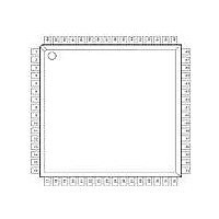
XR16C854IV-F Exar Corporation, XR16C854IV-F Datasheet - Page 7

XR16C854IV-F
Manufacturer Part Number
XR16C854IV-F
Description
IC UART FIFO 128B QUAD 64LQFP
Manufacturer
Exar Corporation
Type
Quad UART with 128-byte FIFOsr
Datasheet
1.XR16C854IV-F.pdf
(54 pages)
Specifications of XR16C854IV-F
Number Of Channels
4, QUART
Package / Case
64-LQFP
Features
*
Fifo's
128 Byte
Protocol
RS232, RS485
Voltage - Supply
2.97 V ~ 5.5 V
With Auto Flow Control
Yes
With Irda Encoder/decoder
Yes
With False Start Bit Detection
Yes
With Modem Control
Yes
With Cmos
Yes
Mounting Type
Surface Mount
Data Rate
2 Mbps
Supply Voltage (max)
5.5 V
Supply Voltage (min)
2.97 V
Supply Current
3 mA to 6 mA
Maximum Operating Temperature
+ 85 C
Minimum Operating Temperature
- 45 C
Mounting Style
SMD/SMT
Operating Supply Voltage
2.97 V to 5.5 V
No. Of Channels
4
Uart Features
Tx/Rx FIFO Counters
Supply Voltage Range
2.97V To 5.5V
Operating Temperature Range
-40°C To +85°C
Digital Ic Case Style
LQFP
Rohs Compliant
Yes
Lead Free Status / RoHS Status
Lead free / RoHS Compliant
Lead Free Status / RoHS Status
Lead free / RoHS Compliant, Lead free / RoHS Compliant
Other names
1016-1276
Available stocks
Company
Part Number
Manufacturer
Quantity
Price
Company:
Part Number:
XR16C854IV-F
Manufacturer:
HYNIX
Quantity:
101
Company:
Part Number:
XR16C854IV-F
Manufacturer:
Exar Corporation
Quantity:
10 000
Pin Description
xr
REV. 3.0.1
ANCILLARY SIGNALS
(RESET#)
CHCCLK
CLKSEL
RESET
16/68#
XTAL1
XTAL2
CDC#
CDD#
CDA#
CDB#
N
RIA#
RIB#
RIC#
RID#
GND
VCC
AME
64-LQFP
4, 35, 52
14, 28,
45, 61
P
64
18
31
49
63
19
30
50
25
26
21
27
IN
-
-
#
68-PLCC
6, 23, 40,
13, 47,
P
27
43
61
28
42
62
35
36
31
30
37
64
57
IN
9
8
-
#
100-QFP
10, 61,
20, 46,
71, 96
P
99
32
49
83
98
33
48
84
40
41
36
35
42
43
86
IN
#
T
Pwr 2.97V to 5.5V power supply. All input pins, except XTAL1, are 5V
Pwr Power supply common, ground.
YPE
O
I
I
I
I
I
I
UART channels A-D Carrier-Detect (active low) or general purpose
input. This input should be connected to VCC when not used.
UART channels A-D Ring-Indicator (active low) or general purpose
input. This input should be connected to VCC when not used.
Crystal or external clock input. This input is not 5V tolerant.
Crystal or buffered clock output.
Intel or Motorola Bus Select (input with internal pull-up).
When 16/68# pin is at logic 1, 16 or Intel Mode, the device will
operate in the Intel bus type of interface.
When 16/68# pin is at logic 0, 68 or Motorola mode, the device will
operate in the Motorola bus type of interface.
Motorola bus interface is not available on the 64 pin package.
Baud-Rate-Generator Input Clock Prescaler Select for channels A-
D. This input is only sampled during power up or a reset. Connect
to VCC for divide by 1 and GND for divide by 4. MCR[7] can over-
ride the state of this pin following a reset or initialization. See MCR
bit-7 and
This input provides the clock for UART channel C. An external
16X baud clock or the crystal oscillator’s output, XTAL2, must be
connected to this pin for normal operation. This input may also be
used with MIDI (Musical Instrument Digital Interface) applications
when an external MIDI clock is provided.
When 16/68# pin is at logic 1 for Intel bus interface, this input
becomes the Reset pin (active high). In this case, a 40 ns mini-
mum logic 1 pulse on this pin will reset the internal registers and all
outputs. The UART transmitter output will be held at logic 1, the
receiver input will be ignored and outputs are reset during reset
period
interface, this input becomes Reset# pin (active low). This pin
functions similarly, but instead of a logic 1 pulse, a 40 ns minimum
logic 0 pulse will reset the internal registers and outputs.
Motorola bus interface is not available on the 64 pin package.
tolerant.
7
(Table
2.97V TO 5.5V QUAD UART WITH 128-BYTE FIFO
Figure 6
18). When 16/68# pin is at a logic 0 for Motorola bus
in the Baud Rate Generator section.
D
ESCRIPTION
XR16C854/854D


