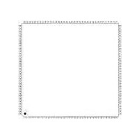
XR17D158CV-F Exar Corporation, XR17D158CV-F Datasheet - Page 30

XR17D158CV-F
Manufacturer Part Number
XR17D158CV-F
Description
IC UART PCI BUS OCTAL 144LQFP
Manufacturer
Exar Corporation
Type
IrDA or RS- 485r
Datasheet
1.XR17D158CV-F.pdf
(73 pages)
Specifications of XR17D158CV-F
Number Of Channels
8
Package / Case
144-LQFP
Features
*
Fifo's
64 Byte
Protocol
RS485
Voltage - Supply
3.3V, 5V
With Auto Flow Control
Yes
With Irda Encoder/decoder
Yes
With False Start Bit Detection
Yes
With Modem Control
Yes
Mounting Type
Surface Mount
Data Rate
6.25 Mbps
Supply Voltage (max)
5.5 V
Supply Voltage (min)
4.5 V
Supply Current
5 mA
Maximum Operating Temperature
+ 70 C
Minimum Operating Temperature
0 C
Mounting Style
SMD/SMT
Operating Supply Voltage
5 V
No. Of Channels
8
Uart Features
Tx/Rx FIFO Counters
Supply Voltage Range
3V To 5.5V
Operating Temperature Range
0°C To +70°C
Digital Ic Case Style
LQFP
No. Of Pins
144
Rohs Compliant
Yes
Lead Free Status / RoHS Status
Lead free / RoHS Compliant
Lead Free Status / RoHS Status
Lead free / RoHS Compliant, Lead free / RoHS Compliant
Other names
1016-1291
Available stocks
Company
Part Number
Manufacturer
Quantity
Price
Company:
Part Number:
XR17D158CV-F
Manufacturer:
Exar Corporation
Quantity:
10 000
Part Number:
XR17D158CV-F
Manufacturer:
EXAR/艾科嘉
Quantity:
20 000
XR17D158
UNIVERSAL (3.3V AND 5V) PCI BUS OCTAL UART
There are 8 UARTs [channels 7:0] in the D158. Each has its own 64-byte of transmit and receive FIFO, a set of
16550 compatible control and status registers, and a baud rate generator for individual channel data rate
setting. Eight additional registers per UART were added for the EXAR enhanced features.
Each UART has its own Baud Rate Generator (BRG) with a prescaler for the transmitter and receiver. The
prescaler is controlled by a software bit in the MCR register. The MCR register bit-7 sets the prescaler to divide
the input crystal or external clock by 1 or 4. The output of the prescaler clocks to the BRG. The BRG further
divides this clock by a programmable divisor between 1 and (2
the serial data rate. The sampling clock is used by the transmitter for data bit shifting and receiver for data
sampling. The BRG divisor (DLL and DLM registers) defaults to a random value upon power up. Therefore, the
BRG must be programmed during initialization to the operating data rate.
Programming the Baud Rate Generator Registers DLM and DLL provides the capability for selecting the
operating data rate.
clock at 16X clock rate. At 8X sampling rate, these data rates would double. When using a non-standard data
rate crystal or external clock, the divisor value can be calculated with the following equation(s).
5.0 UART
5.1
divisor (decimal) = (XTAL1 clock frequency / prescaler) / (serial data rate x 16),
divisor (decimal) = (XTAL1 clock frequency / prescaler / (serial data rate x 8),
Programmable Baud Rate Generator
F
IGURE
XTAL1
XTAL2
Table 10
11. B
AUD
shows the standard data rates available with a 14.7456 MHz crystal or external
Crystal
Buffer
Osc/
R
ATE
Channels
To Other
G
ENERATOR
Divide by 4
Divide by 1
Prescaler
Prescaler
30
MCR Bit-7=1
MCR Bit-7=0
(default)
16
-1) to obtain a 16X or 8X sampling clock of
Baud Rate
DLL and DLM
Generator
Registers
Logic
WITH
WITH
8XMODE [7:0]
8XMODE [7:0]
Rate Clock to
and Receiver
Transmitter
16X or 8X
Sampling
IS
IS
1
xr
0
REV. 1.2.2


