STEVAL-PCC012V1 STMicroelectronics, STEVAL-PCC012V1 Datasheet - Page 47
STEVAL-PCC012V1
Manufacturer Part Number
STEVAL-PCC012V1
Description
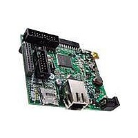
BOARD DEM CONN GATEWAY STM32F107
Manufacturer
STMicroelectronics
Series
STM32r
Type
Other Power Managementr
Datasheets
1.STM32F105V8T6.pdf
(101 pages)
2.STEVAL-PCC012V1.pdf
(10 pages)
3.EVALST7590-1.pdf
(43 pages)
Specifications of STEVAL-PCC012V1
Main Purpose
Interface, Connectivity
Embedded
Yes, MCU, 32-Bit
Utilized Ic / Part
STM32F107
Primary Attributes
Ethernet and 4 Digital/Analog Connectors
Secondary Attributes
On-Board LEDs and Joystick
Interface Type
Ethernet, USB, I2C, SPI, UART
Operating Supply Voltage
3.3 V
Product
Power Management Development Tools
Lead Free Status / RoHS Status
Lead free / RoHS Compliant
For Use With/related Products
STM32F107xx
Other names
497-10757
Available stocks
Company
Part Number
Manufacturer
Quantity
Price
Company:

Part Number:
STEVAL-PCC012V1
Manufacturer:
STMicroelectronics
Quantity:
1


STM32F105xx, STM32F107xx
Table 22.
1. Resonator characteristics given by the crystal/ceramic resonator manufacturer.
2. Based on characterization, not tested in production.
3. The relatively low value of the RF resistor offers a good protection against issues resulting from use in a
4. t
For C
5 pF to 25 pF range (typ.), designed for high-frequency applications, and selected to match
the requirements of the crystal or resonator (see
same size. The crystal manufacturer typically specifies a load capacitance which is the
series combination of C
can be used as a rough estimate of the combined pin and board capacitance) when sizing
C
microcontrollers” available from the ST website www.st.com.
Figure 16. Typical application with an 8 MHz crystal
1. R
Low-speed external clock generated from a crystal/ceramic resonator
The low-speed external (LSE) clock can be supplied with a 32.768 kHz crystal/ceramic
resonator oscillator. All the information given in this paragraph are based on characterization
results obtained with typical external components specified in
the resonator and the load capacitors have to be placed as close as possible to the oscillator
pins in order to minimize output distortion and startup stabilization time. Refer to the crystal
t
SU(HSE
Symbol
L1
f
OSC_IN
humid environment, due to the induced leakage and the bias condition change. However, it is
recommended to take this point into account if the MCU is used in tough humidity conditions.
oscillation is reached. This value is measured for a standard crystal resonator and it can vary significantly
with the crystal manufacturer
Resonator with
integrated capacitors
SU(HSE)
R
g
and C
C
EXT
i
2
m
F
L1
(4)
value depends on the crystal characteristics.
and C
is the startup time measured from the moment it is enabled (by software) to a stabilized 8 MHz
L2
Oscillator frequency
Feedback resistor
Recommended load capacitance
versus equivalent serial
resistance of the crystal (R
HSE driving current
Oscillator transconductance
Startup time
. Refer to the application note AN2867 “Oscillator design guide for ST
HSE 3-25 MHz oscillator characteristics
L2
C L2
, it is recommended to use high-quality external ceramic capacitors in the
C L1
Parameter
L1
8 MH z
resonator
R EXT (1)
and C
Doc ID 15274 Rev 5
L2
. PCB and MCU pin capacitance must be included (10 pF
OSC_OU T
OSC_IN
S
)
(3)
V
R F
DD
V
with 30 pF load
= 3.3 V, V
DD
Conditions
controlled
R
Figure
Startup
Bias
S
is stabilized
gain
= 30
(1) (2)
IN
16). C
= V
SS
STM32F10xxx
Table
L1
Electrical characteristics
and C
f HSE
Min
25
3
23. In the application,
L2
Typ
200
30
2
are usually the
Max
25
1
ai14128b
mA/V
47/101
MHz
Unit
mA
ms
k
pF
Related parts for STEVAL-PCC012V1
Image
Part Number
Description
Manufacturer
Datasheet
Request
R

Part Number:
Description:
Interface Development Tools Opto ISO USB Bridge 8-Pin Motor CTRL BRD
Manufacturer:
STMicroelectronics
Datasheet:

Part Number:
Description:
BOARD EVAL FOR MEMS SENSORS
Manufacturer:
STMicroelectronics
Datasheet:
Part Number:
Description:
EVALBOARD/STEVAL-ISV014V1
Manufacturer:
STMicroelectronics
Part Number:
Description:
BOARD EVAL FOR ST802RT1
Manufacturer:
STMicroelectronics
Datasheet:

Part Number:
Description:
BOARD EVAL FOR VACUUM CLEANER
Manufacturer:
STMicroelectronics
Datasheet:

Part Number:
Description:
KIT DEV STARTER ST10F276Z5
Manufacturer:
STMicroelectronics
Datasheet:

Part Number:
Description:
BOARD LED CTLR/DVR STLED316S
Manufacturer:
STMicroelectronics
Datasheet:

Part Number:
Description:
BOARD EVAL BLDC SENSORLESS MOTOR
Manufacturer:
STMicroelectronics
Datasheet:

Part Number:
Description:
BOARD ELECT FISCAL CASH REGISTER
Manufacturer:
STMicroelectronics
Datasheet:

Part Number:
Description:
BOARD EVAL BIPO SOLUTION FOR PFC
Manufacturer:
STMicroelectronics
Datasheet:
Part Number:
Description:
STMicroelectronics [RIPPLE-CARRY BINARY COUNTER/DIVIDERS]
Manufacturer:
STMicroelectronics
Datasheet:
Part Number:
Description:
STMicroelectronics [LIQUID-CRYSTAL DISPLAY DRIVERS]
Manufacturer:
STMicroelectronics
Datasheet:
Part Number:
Description:
BOARD EVAL FOR MEMS SENSORS
Manufacturer:
STMicroelectronics
Datasheet: