TWR-K40X256 Freescale Semiconductor, TWR-K40X256 Datasheet - Page 10
TWR-K40X256
Manufacturer Part Number
TWR-K40X256
Description
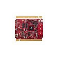
TOWER SYSTEM BOARD K40X256
Manufacturer
Freescale Semiconductor
Series
Kinetisr
Type
MCUr
Specifications of TWR-K40X256
Contents
Board
Processor To Be Evaluated
K40
Data Bus Width
32 bit
Interface Type
USB, CAN, I2C, SPI, UART
Dimensions
3.5 in x 3.2 in
Operating Supply Voltage
1.71 V to 3.6 V
Silicon Manufacturer
Freescale
Core Architecture
ARM
Core Sub-architecture
Cortex - M4
Silicon Core Number
MK
Silicon Family Name
Kinetis - K40
Kit Contents
Board Only
Rohs Compliant
Yes
For Use With/related Products
Freescale Tower System, K40X256
Lead Free Status / RoHS Status
Lead free / RoHS Compliant


2.3 System Power
In stand-alone operation, the power source for the TWR-K40X256 module is derived from the 5.0V
input from either the USB mini-B connector, J16, or the debug header, J14, when a shunt is placed on
jumper J15. A low-dropout regulator provides a 3.3V supply from the 5.0V input voltage. Refer to
sheet 5 of the TWR-K40X256 schematics for more details.
When installed into a Tower System, the TWR-K40X256 can be powered from either an on-board
source or from another source in the assembled Tower System. If both the on-board and off-board
sources are available, the TWR-K40X256 will default to the off-board source.
The 3.3V power supplied to the MCU is routed through a jumper, J11. The jumper shunt can be
removed to allow for either 1) alternate MCU supply voltages to be injected or 2) the measurement of
power consumed by the MCU.
2.3.1 RTC VBAT
The Real Time Clock (RTC) module on the K40 has two modes of operation, system power-up and
system power-down. During system power-down, the RTC is powered from the backup power supply,
VBAT. The TWR-K40X256 provides a battery holder for a coin cell battery that can be used as the VBAT
supply. The holder can accept common 20mm diameter 3V lithium coin cell batteries (e.g. 2032,
2025). Refer to the description J12 in Table 5 “TWR-K40X256 Jumper Table” for more information.
2.4 Debug Interface
There are two debug interface options provided: the on-board OSJTAG circuit and an external Cortex
Debug+ETM connector.
2.4.1 OSJTAG
An on-board MC9S08JM60 based Open Source JTAG (OSJTAG) circuit provides a JTAG debug interface
to the K40X256. A standard USB A male to Mini-B male cable (provided) can be used for debugging via
the USB connector, J16. The OSJTAG interface also provides a USB to serial bridge. Drivers for the
OSJTAG interface are provided in the P&E Micro Kinetis Tower Toolkit (available on the included DVD).
Note: The port pins connected to the OSJTAG USB-to-serial bridge (PTD6 and PTD7) are also connected
to the infrared interface. Refer to Table 6 “I/O Connectors and Pin Usage Table” and Table 5 “TWR-
K40X256 Jumper Table” for more information.
8.0 MHz Resonator
32.768 KHz RTC Crystal
Clock Input from CLKIN0
"X" indicates that the resistor is installed; "―" indicates that the resistor is not
populated. All resistor values are 0 ohm.
MCG Oscillator Input
TWR-K40X256 Tower Module User's Manual
Table 1. MCG oscillator input selection resistor settings
R93 R91 R95 R97 R81 R88 R87 R86 R83 R84
―
X
X
―
―
X
―
X
X
―
―
X
―
―
X
―
―
X
―
―
X
Page 10 of 21
―
―
X
―
―
X
―
―
X
Related parts for TWR-K40X256
Image
Part Number
Description
Manufacturer
Datasheet
Request
R

Part Number:
Description:
TOWER SYSTEM KIT K40X256
Manufacturer:
Freescale Semiconductor
Datasheet:

Part Number:
Description:
K53N512CMD100 TWR Module
Manufacturer:
Freescale Semiconductor
Datasheet:
Part Number:
Description:
TWR-K53N512 Dev Kit
Manufacturer:
Freescale Semiconductor
Datasheet:

Part Number:
Description:
CONV DC/DC TRI OUT 5,15,-15V
Manufacturer:
Murata Power Solutions Inc
Datasheet:

Part Number:
Description:
CONV DC/DC TRI OUT 5,12,-12V
Manufacturer:
Murata Power Solutions Inc
Datasheet:

Part Number:
Description:
CONV DC/DC TRI OUT 5,15,-15V
Manufacturer:
Murata Power Solutions Inc
Datasheet:

Part Number:
Description:
LCD MODULE FOR TWR SYSTEM
Manufacturer:
Freescale Semiconductor
Datasheet:

Part Number:
Description:
DC/DC TH 11W 5-5/12V Triple A
Manufacturer:
Murata Power Solutions Inc
Datasheet:


Part Number:
Description:
TOWER SYSTEM PROTO
Manufacturer:
Freescale Semiconductor
Datasheet:

Part Number:
Description:
TOWER ELEVATOR BOARDS HARDWARE
Manufacturer:
Freescale Semiconductor
Datasheet:

Part Number:
Description:
TOWER SERIAL I/O HARDWARE
Manufacturer:
Freescale Semiconductor
Datasheet:

Part Number:
Description:
TOWER SYSTEM BOARD MPC5125
Manufacturer:
Freescale Semiconductor
Datasheet: