TWR-K40X256 Freescale Semiconductor, TWR-K40X256 Datasheet - Page 14
TWR-K40X256
Manufacturer Part Number
TWR-K40X256
Description
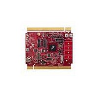
TOWER SYSTEM BOARD K40X256
Manufacturer
Freescale Semiconductor
Series
Kinetisr
Type
MCUr
Specifications of TWR-K40X256
Contents
Board
Processor To Be Evaluated
K40
Data Bus Width
32 bit
Interface Type
USB, CAN, I2C, SPI, UART
Dimensions
3.5 in x 3.2 in
Operating Supply Voltage
1.71 V to 3.6 V
Silicon Manufacturer
Freescale
Core Architecture
ARM
Core Sub-architecture
Cortex - M4
Silicon Core Number
MK
Silicon Family Name
Kinetis - K40
Kit Contents
Board Only
Rohs Compliant
Yes
For Use With/related Products
Freescale Tower System, K40X256
Lead Free Status / RoHS Status
Lead free / RoHS Compliant


2.10 Segment LCD
The segment LCD signals on the K40 devices are multiplexed with many other interface signals
including several TSI signals that are accessible on the Touch TWRPI socket. Therefore, the Touch
TWRPI socket on the TWR-K40X256 may also be used to evaluate the segment LCD controller of the
K40 device. The TWRPI-SLCD daughter card included with the TWR-K40X256 plugs into the Touch
TWRPI socket and provides a 28-segment LCD that can be driven directly by the K40 MCU. Refer to
Table 6 “I/O Connectors and Pin Usage Table” for the segment LCD signals connection details.
Additionally, many more segment LCD signals are routed to the Secondary Connector on the TWR-
K40X256 and can be accessed from another Tower module or on the expansion connectors of the
Secondary Elevator. Refer to Table 8 “TWR-K40X256 Secondary Connector Pinout” for connection
details.
2.11 USB
The K40X256 features a USB full-speed/low-speed OTG/Host/Device controller with built-in
transceiver. The TWR-K40X256 routes the USB D+ and D- signals from the K40 MCU to the Primary
Connector, allowing the connection to USB connectors or additional circuitry on a Tower peripheral
module.
The TWR-SER module included as part of the TWR-K40X256-KIT provides a USB OTG/Host/Device
interface with a mini-AB USB connector. There are many configuration options that can be selected to
evaluate different USB modes of operation. By default, the TWR-SER is configured for USB Device
operation. Please refer to the documentation included with the TWR-SER for more information on the
configuration options.
2.12 Secure Digital Card Slot
A Secure Digital (SD) card slot is available on the TWR-K40X256 connected to the SD Host Controller
(SDHC) signals of the K40 MCU. This slot will accept SD memory cards as well as Secure Digital Input
Output (SDIO) cards. Refer to Table 6 “I/O Connectors and Pin Usage Table” for the SDHC signal
connection details.
TWR-K40X256 Tower Module User's Manual
Pin
8
9
10
11
12
13
14
15
16
17
18
19
20
Description
Electrode 3
Electrode 4
Electrode 5
Electrode 6
Electrode 7
Electrode 8
Electrode 9
Electrode 10
Electrode 11
ADC: TWRPI ID 0
ADC: TWRPI ID 1
GND
Reset
Page 14 of 21
Related parts for TWR-K40X256
Image
Part Number
Description
Manufacturer
Datasheet
Request
R

Part Number:
Description:
TOWER SYSTEM KIT K40X256
Manufacturer:
Freescale Semiconductor
Datasheet:

Part Number:
Description:
K53N512CMD100 TWR Module
Manufacturer:
Freescale Semiconductor
Datasheet:
Part Number:
Description:
TWR-K53N512 Dev Kit
Manufacturer:
Freescale Semiconductor
Datasheet:

Part Number:
Description:
CONV DC/DC TRI OUT 5,15,-15V
Manufacturer:
Murata Power Solutions Inc
Datasheet:

Part Number:
Description:
CONV DC/DC TRI OUT 5,12,-12V
Manufacturer:
Murata Power Solutions Inc
Datasheet:

Part Number:
Description:
CONV DC/DC TRI OUT 5,15,-15V
Manufacturer:
Murata Power Solutions Inc
Datasheet:

Part Number:
Description:
LCD MODULE FOR TWR SYSTEM
Manufacturer:
Freescale Semiconductor
Datasheet:

Part Number:
Description:
DC/DC TH 11W 5-5/12V Triple A
Manufacturer:
Murata Power Solutions Inc
Datasheet:


Part Number:
Description:
TOWER SYSTEM PROTO
Manufacturer:
Freescale Semiconductor
Datasheet:

Part Number:
Description:
TOWER ELEVATOR BOARDS HARDWARE
Manufacturer:
Freescale Semiconductor
Datasheet:

Part Number:
Description:
TOWER SERIAL I/O HARDWARE
Manufacturer:
Freescale Semiconductor
Datasheet:

Part Number:
Description:
TOWER SYSTEM BOARD MPC5125
Manufacturer:
Freescale Semiconductor
Datasheet: