TWR-K40X256 Freescale Semiconductor, TWR-K40X256 Datasheet - Page 15
TWR-K40X256
Manufacturer Part Number
TWR-K40X256
Description
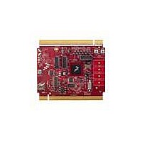
TOWER SYSTEM BOARD K40X256
Manufacturer
Freescale Semiconductor
Series
Kinetisr
Type
MCUr
Specifications of TWR-K40X256
Contents
Board
Processor To Be Evaluated
K40
Data Bus Width
32 bit
Interface Type
USB, CAN, I2C, SPI, UART
Dimensions
3.5 in x 3.2 in
Operating Supply Voltage
1.71 V to 3.6 V
Silicon Manufacturer
Freescale
Core Architecture
ARM
Core Sub-architecture
Cortex - M4
Silicon Core Number
MK
Silicon Family Name
Kinetis - K40
Kit Contents
Board Only
Rohs Compliant
Yes
For Use With/related Products
Freescale Tower System, K40X256
Lead Free Status / RoHS Status
Lead free / RoHS Compliant


2.13 External Bus Interface – FlexBus
The K40 device features a multi-function external bus interface called the FlexBus interface controller
capable of interfacing to slave-only devices. The FlexBus interface is not used directly on the TWR-
K40X256. Instead, a subset of the FlexBus is connected to the Primary Connector so that the external
bus can access devices on Tower peripheral modules.
The Primary Connector supports up to 20 address lines, 8 data lines, 2 chip-selects, read/write, and
output enable signals. The SDHC signals of the K40 are multiplexed over the upper FlexBus address
signals (FB_AD[27:23]), so a multiplexed mode of operation is used on the TWR-K40X256. An address
latch is provided to de-multiplex the address and data signals prior to connecting them to the Primary
Connector. Refer to sheet 8 of the TWR-K40X256 schematics for more details.
Note: The K40 Flexbus implementation provides an option for byte lane alignment. On the TWR-
K40X256, FB_AD[7:0] are used for the data byte. Therefore, for proper operation software must set the
CSCRx[BLS] bit to shift the data bus to the right byte lane. Refer to the FlexBus chapter in the K40
Family Reference Manual for more information.
3 Jumper Table
There are several jumpers on the TWR-K40X256 that provide configuration selection and signal
isolation. Refer to the following table for details. The default installed jumper settings are shown in
bold with asterisks.
Jumper
J11
J3
J5
J6
Figure 8. Flexbus Connections for External Memory Port Sizes (CSCRn[BLS] = 1)
USB VREGIN Power
Connection
Flexbus Address Latch
Selection
Infrared Transmitter
Connection
MCU Power Connection
Option
TWR-K40X256 Tower Module User's Manual
Table 5. TWR-K40X256 Jumper Table
Setting
*OFF*
*ON*
*2-3*
*ON*
OFF
1-2
ON
Connect USB0_VBUS from Primary Elevator (A57) to VREGIN
Disconnect VREGIN from Primary Elevator
Flexbus address latch disabled
Flexbus address latch enabled
Connect PTD7/CMT_IRO/UART0_TX to IR Transmitter (D3)
Disconnect PTD7/CMT_IRO/UART0_TX from IR Transmitter (D3)
Connect on-board 3.3V supply to MCU
Description
Page 15 of 21
Related parts for TWR-K40X256
Image
Part Number
Description
Manufacturer
Datasheet
Request
R

Part Number:
Description:
TOWER SYSTEM KIT K40X256
Manufacturer:
Freescale Semiconductor
Datasheet:

Part Number:
Description:
K53N512CMD100 TWR Module
Manufacturer:
Freescale Semiconductor
Datasheet:
Part Number:
Description:
TWR-K53N512 Dev Kit
Manufacturer:
Freescale Semiconductor
Datasheet:

Part Number:
Description:
CONV DC/DC TRI OUT 5,15,-15V
Manufacturer:
Murata Power Solutions Inc
Datasheet:

Part Number:
Description:
CONV DC/DC TRI OUT 5,12,-12V
Manufacturer:
Murata Power Solutions Inc
Datasheet:

Part Number:
Description:
CONV DC/DC TRI OUT 5,15,-15V
Manufacturer:
Murata Power Solutions Inc
Datasheet:

Part Number:
Description:
LCD MODULE FOR TWR SYSTEM
Manufacturer:
Freescale Semiconductor
Datasheet:

Part Number:
Description:
DC/DC TH 11W 5-5/12V Triple A
Manufacturer:
Murata Power Solutions Inc
Datasheet:


Part Number:
Description:
TOWER SYSTEM PROTO
Manufacturer:
Freescale Semiconductor
Datasheet:

Part Number:
Description:
TOWER ELEVATOR BOARDS HARDWARE
Manufacturer:
Freescale Semiconductor
Datasheet:

Part Number:
Description:
TOWER SERIAL I/O HARDWARE
Manufacturer:
Freescale Semiconductor
Datasheet:

Part Number:
Description:
TOWER SYSTEM BOARD MPC5125
Manufacturer:
Freescale Semiconductor
Datasheet: