ATAKSTK511-3 Atmel, ATAKSTK511-3 Datasheet - Page 27
ATAKSTK511-3
Manufacturer Part Number
ATAKSTK511-3
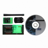
Description
KIT RF MODULE 315MHZ FOR STK500
Manufacturer
Atmel
Series
SmartRF®r
Type
Transmitter, Receiver, ASK, FSKr
Specifications of ATAKSTK511-3
Frequency
433MHz
Wireless Frequency
315 MHz
For Use With/related Products
ATSTK500
Lead Free Status / RoHS Status
Contains lead / RoHS non-compliant
Other names
Q2262874


4842B–AVR–10/09
STK511 Transmitter Board
5-4
Keying Circuit: RF transmission from the T575x is controlled by signals on its two ports ENABLE and
PA_ENABLE. These signals originate from the ATtiny13's ports PB4 and PB1, respectively.
With this straightforward, two-line control, ASK modulation (or in most cases OOK), is easily imple-
mented in the microcontroller software. When the T575x’s ENABLE port is taken high by port PB4, the
transmitter is activated. Then, RF energy is transmitted when port PB1 pulls PA_ENABLE high. Requir-
ing that two ports on the T575x be pulled high in order to emit RF energy helps prevent accidental
transmissions.
Manchester-encoded OOK transmission is achieved, for example, by taking the T575x’s PA_ENABLE
high during one-half of the bit interval, then allowing it to go low during the other half of the bit interval (or,
vice-versa).
Crystal Oscillator: The crystal, X1, along with capacitors C6 and C7, determines the transmit frequency
of the STK511 transmitter. C7 is the manufacturer-specified load capacitor for the crystal used. It places
the transmitter at the main frequency of operation (e.g., 315 MHz, 433.92 MHz, etc.), for ASK/FSK mod-
ulation, f0. With microcontroller port PB0, C6 is switched in-and-out of a parallel combination with C7 to
generate an FSK-modulated signal. When configured as an input, PB0 is in a hi-Z tri-state condition and
C6 is not part of the crystal's capacitive load. C6 is provided a path to ground, placing it in parallel with
C7, when PB0 is changed to an output low. This additional load capacitance shifts the frequency of the
crystal oscillator circuit lower, providing the second frequency of FSK modulation, f1. Adjusting the value
of C6 can easily set the amount of shift, f0 - f1. For this particular transmitter, the shift is on the order of
40 kHz.
If desired, switching C6 into and out-of parallel with C7 can also be done with an external JFET at U3.
The SST211 is a low-capacitance, enhancement-mode JFET that works well in this application.
For Manchester-encoded FSK transmission, the T575x’s PA_ENABLE is held high during both the
halves of the bit interval. C6 is switched in-and-out appropriately for each bit-interval half to create the
frequency-shifted modulation.
STK511 User Guide
Related parts for ATAKSTK511-3
Image
Part Number
Description
Manufacturer
Datasheet
Request
R

Part Number:
Description:
DEV KIT FOR AVR/AVR32
Manufacturer:
Atmel
Datasheet:

Part Number:
Description:
INTERVAL AND WIPE/WASH WIPER CONTROL IC WITH DELAY
Manufacturer:
ATMEL Corporation
Datasheet:
Part Number:
Description:
Low-Voltage Voice-Switched IC for Hands-Free Operation
Manufacturer:
ATMEL Corporation
Datasheet:
Part Number:
Description:
MONOLITHIC INTEGRATED FEATUREPHONE CIRCUIT
Manufacturer:
ATMEL Corporation
Datasheet:
Part Number:
Description:
AM-FM Receiver IC U4255BM-M
Manufacturer:
ATMEL Corporation
Datasheet:
Part Number:
Description:
Monolithic Integrated Feature Phone Circuit
Manufacturer:
ATMEL Corporation
Datasheet:
Part Number:
Description:
Multistandard Video-IF and Quasi Parallel Sound Processing
Manufacturer:
ATMEL Corporation
Datasheet:
Part Number:
Description:
High-performance EE PLD
Manufacturer:
ATMEL Corporation
Datasheet:
Part Number:
Description:
8-bit Flash Microcontroller
Manufacturer:
ATMEL Corporation
Datasheet:
Part Number:
Description:
2-Wire Serial EEPROM
Manufacturer:
ATMEL Corporation
Datasheet: