ATAKSTK511-3 Atmel, ATAKSTK511-3 Datasheet - Page 35
ATAKSTK511-3
Manufacturer Part Number
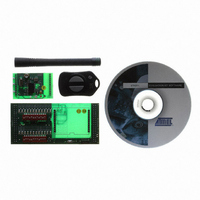
ATAKSTK511-3
Description
KIT RF MODULE 315MHZ FOR STK500
Manufacturer
Atmel
Series
SmartRF®r
Type
Transmitter, Receiver, ASK, FSKr
Specifications of ATAKSTK511-3
Frequency
433MHz
Wireless Frequency
315 MHz
For Use With/related Products
ATSTK500
Lead Free Status / RoHS Status
Contains lead / RoHS non-compliant
Other names
Q2262874


4842B–AVR–10/09
Troubleshooting Guide
7-2
Table 7-1. Troubleshooting Solutions (Continued)
Problem
Registers in the receiver do not
appear to be programming
Unable to load Receiver Interface
Board firmware
Transmitter not responding to
button press
No activity on Transmitter
Application Board LED(s)
Reason
Power supplied is too low
DATA Selector switch was not set to
the STK511 position when
Configure button pressed
Receiver Interface Board firmware
has become corrupted
Registers may be programming
correctly with no visible signs of
change
Some external source may be
holding the Data line low
Receiver Application Board rotated
180° when mounted on the
Receiver Interface Board
Receiver Interface Board not
correctly connected to STK500
ISP ribbon cable not connected
properly
Incorrect device selected
Device present in STK500 sockets
ISP jumper not shorted on Receiver
Interface Board
Power and serial cable not
connected to STK500
Battery dead
Demo Software corrupted
Switch contact not made
Low Battery voltage
Transmitter is in sleep mode
Demo Software corrupted
Solution
Verify that the power being supplied
is 5V
Set DATA Selector switch to
STK511 and re-press button
Reload the Receiver Interface
Board Firmware as described in
section
on page 3-3
Monitor the Data Testpoint with an
oscilloscope to check for presence
of the acknowledge bit
Verify that Receiver Application
Board signal testpoints are toward
the DIP switches.
Verify EXPAND0 and EXPAND1 are
properly oriented
Ensure ribbon cable connected
between ISP6PIN header and
SPROG3 header
Check orientation of pin 1 on
headers
Select ATmega8515 from the
Device menu. Verify that the
signature byte matches in the
Advanced tab
Remove all devices from the
programming sockets of the
STK500
Connect shunt
Verify setup of the STK500
hardware
Open Transmitter Application Board
case and replace coin cell battery
Reload the desired software
according to section
Description” on page 4-6
Ensure proper contact of the button
to the Transmitter Application Board
Replace coin cell battery
Press button to wake from sleep
mode
Reload the desired software
according to section
Description” on page 4-6
“Software Description”
STK511 User Guide
“Software
“Software
Related parts for ATAKSTK511-3
Image
Part Number
Description
Manufacturer
Datasheet
Request
R

Part Number:
Description:
DEV KIT FOR AVR/AVR32
Manufacturer:
Atmel
Datasheet:

Part Number:
Description:
INTERVAL AND WIPE/WASH WIPER CONTROL IC WITH DELAY
Manufacturer:
ATMEL Corporation
Datasheet:
Part Number:
Description:
Low-Voltage Voice-Switched IC for Hands-Free Operation
Manufacturer:
ATMEL Corporation
Datasheet:
Part Number:
Description:
MONOLITHIC INTEGRATED FEATUREPHONE CIRCUIT
Manufacturer:
ATMEL Corporation
Datasheet:
Part Number:
Description:
AM-FM Receiver IC U4255BM-M
Manufacturer:
ATMEL Corporation
Datasheet:
Part Number:
Description:
Monolithic Integrated Feature Phone Circuit
Manufacturer:
ATMEL Corporation
Datasheet:
Part Number:
Description:
Multistandard Video-IF and Quasi Parallel Sound Processing
Manufacturer:
ATMEL Corporation
Datasheet:
Part Number:
Description:
High-performance EE PLD
Manufacturer:
ATMEL Corporation
Datasheet:
Part Number:
Description:
8-bit Flash Microcontroller
Manufacturer:
ATMEL Corporation
Datasheet:
Part Number:
Description:
2-Wire Serial EEPROM
Manufacturer:
ATMEL Corporation
Datasheet: