ATAKSTK511-3 Atmel, ATAKSTK511-3 Datasheet - Page 8
ATAKSTK511-3
Manufacturer Part Number
ATAKSTK511-3
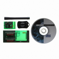
Description
KIT RF MODULE 315MHZ FOR STK500
Manufacturer
Atmel
Series
SmartRF®r
Type
Transmitter, Receiver, ASK, FSKr
Specifications of ATAKSTK511-3
Frequency
433MHz
Wireless Frequency
315 MHz
For Use With/related Products
ATSTK500
Lead Free Status / RoHS Status
Contains lead / RoHS non-compliant
Other names
Q2262874


2.3.2
2.3.3
2.4
STK511 User Guide
STK511 Receiver Interface Board Configuration
Using the Transmitter
Evaluating the Demo
1. Verify that the Receiver Application Board has been inserted into the appropriate sockets on the
2. Connect the STK511 Receiver Interface Board to the STK500 by aligning EXPAND0 and EXPAND1
3. Switch the Data Selector switch to the STK511 position.
4. Verify power is supplied to the STK500 board.
The Transmitter Application Board as shipped will be set to run with the default receiver configuration
register settings. The DIP switches on the STK511 Receiver Interface Board should be set according to
the following values:
OPMODE register:
LIMIT register:
Note:
5. Once the DIP switches have been properly set, press the Configure button to write these values into
6. Switch the Data Selector switch to the STK500 position and the receiver is now ready to pass data
To conserve battery life, the transmitter is shipped in a low current sleep mode. Pressing one of the two
buttons will awaken the transmitter from its sleep mode and initiate periodic data transmissions corre-
sponding to the level of ambient light. Simultaneously pressing both buttons will toggle the modulation
between ASK and FSK modes. If both LEDs blink during transmission then FSK is selected. If only one
LED blinks while transmitting then ASK modulation is selected. The periodic RF transmission rate can be
selected to occur quickly or slowly. Pressing one of the buttons results in a transmission rate of once
every ¼ second while pressing the other button results in a transmission once every 8 seconds. The
transmissions occur after the button is released. The transmitter enters a “sleep” mode after 30 seconds
of activity.
It is possible to reprogram the transmitter via the supplied 6-pin header. For more information on how
this is done,
Once the system is set up, operation is straightforward. The transmitter will send light intensity informa-
tion data periodically. This will be displayed as a bar graph using the LEDs on the STK500. For real-time
updates, set the transmission rate to ¼ second intervals on the transmitter. Slowly cover up the transmit-
ter to view the LED bar graph change in response to changes in light intensity. Conversely, exposing the
transmitter to a light source will cause the LED bar graph to illuminate more LEDs.
It is also possible to view the data being sent by connecting an oscilloscope to the test point on the
Receiver Application Board labeled DATA. This test point can also be used to view the programming
commands when the Configure button is pressed.
STK511 Receiver Interface Board.
connectors and pressing together.
the receiver's registers.
from the transmitter to the STK500 for decoding.
The default values are also shown on the bottom line of the silkscreen on the STK511 board.
See “Hardware Description” on page
DIP switch #1….………..#12
000100011001
010101101001
5-1..
Getting Started
4842B–AVR–10/09
2-3
Related parts for ATAKSTK511-3
Image
Part Number
Description
Manufacturer
Datasheet
Request
R

Part Number:
Description:
DEV KIT FOR AVR/AVR32
Manufacturer:
Atmel
Datasheet:

Part Number:
Description:
INTERVAL AND WIPE/WASH WIPER CONTROL IC WITH DELAY
Manufacturer:
ATMEL Corporation
Datasheet:
Part Number:
Description:
Low-Voltage Voice-Switched IC for Hands-Free Operation
Manufacturer:
ATMEL Corporation
Datasheet:
Part Number:
Description:
MONOLITHIC INTEGRATED FEATUREPHONE CIRCUIT
Manufacturer:
ATMEL Corporation
Datasheet:
Part Number:
Description:
AM-FM Receiver IC U4255BM-M
Manufacturer:
ATMEL Corporation
Datasheet:
Part Number:
Description:
Monolithic Integrated Feature Phone Circuit
Manufacturer:
ATMEL Corporation
Datasheet:
Part Number:
Description:
Multistandard Video-IF and Quasi Parallel Sound Processing
Manufacturer:
ATMEL Corporation
Datasheet:
Part Number:
Description:
High-performance EE PLD
Manufacturer:
ATMEL Corporation
Datasheet:
Part Number:
Description:
8-bit Flash Microcontroller
Manufacturer:
ATMEL Corporation
Datasheet:
Part Number:
Description:
2-Wire Serial EEPROM
Manufacturer:
ATMEL Corporation
Datasheet: