ATAKSTK511-3 Atmel, ATAKSTK511-3 Datasheet - Page 6
ATAKSTK511-3
Manufacturer Part Number
ATAKSTK511-3
Description
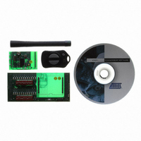
KIT RF MODULE 315MHZ FOR STK500
Manufacturer
Atmel
Series
SmartRF®r
Type
Transmitter, Receiver, ASK, FSKr
Specifications of ATAKSTK511-3
Frequency
433MHz
Wireless Frequency
315 MHz
For Use With/related Products
ATSTK500
Lead Free Status / RoHS Status
Contains lead / RoHS non-compliant
Other names
Q2262874


2.1
2.2
STK511 User Guide
Setting up the Hardware
Configuring the Receiver
The STK
system. Included are the STK511Interface Board, RF Receiver Application Board, and RF Transmitter
Application Board.
The Receiver Application Board should be oriented with its signal pins toward the DIP switches and
LEDs on the STK511 Receiver Interface Board. This places the power and ground test points on the top
of the receiver board adjacent to the DATA selector switch. Insert the receiver board into the provided
connectors.
If the STK511 Receiver Interface Board is used as an expansion card for the STK500, align the
EXPAND0 and EXPAND1 connectors with the corresponding EXPAND0 and EXPAND1 headers on the
STK500 and press together. Be cautious of pinching any ribbon cable ends on the STK500 board when
inserting the STK511 Receiver Interface Board into the connectors.
Once the Receiver Application Board has been inserted into both twelve-pin connectors, power must be
supplied in one of two ways:
A) the power and ground pins on the Receiver Application Board can be connected to a +5V supply, or
B) the supply can be sourced through the STK500 connectors EXPAND0 and EXPAND1.
If the STK500 is used to source power, the VTARGET jumper (located on the STK500) must be con-
nected and VTARGET set to 5V in the STK500 board settings located under the appropriate tab in AVR
Studio
Atmel RF Receivers designated ATA5743, ATA5760 and ATA5761 contain two configuration registers
(Atmel RF receiver designated ATA5744 does not). These registers control the digital processing of the
incoming RF signal, as well as define the receivers’ polling interval. The register values are stored in vol-
atile memory and are lost when power is removed; therefore, they must be re-programmed every time
power is applied. Programming is achieved with a one-wire protocol using the receivers’ DATA line. This
line is bi-directional and is also used for providing the demodulated data to the user. More detail on this
can be found in the individual receivers’ datasheets.
With this in mind, the user must decide how to configure the receiver for the intended application. To
illustrate this process, the following example will show how to change the receiver to ASK from its default
mode of FSK.
®
, Atmel's software development tool.
®
511 Starter Kit comes complete with all the hardware needed to demonstrate a working RF
Getting Started
Section 2
4842B–AVR–10/09
2-1
Related parts for ATAKSTK511-3
Image
Part Number
Description
Manufacturer
Datasheet
Request
R

Part Number:
Description:
DEV KIT FOR AVR/AVR32
Manufacturer:
Atmel
Datasheet:

Part Number:
Description:
INTERVAL AND WIPE/WASH WIPER CONTROL IC WITH DELAY
Manufacturer:
ATMEL Corporation
Datasheet:
Part Number:
Description:
Low-Voltage Voice-Switched IC for Hands-Free Operation
Manufacturer:
ATMEL Corporation
Datasheet:
Part Number:
Description:
MONOLITHIC INTEGRATED FEATUREPHONE CIRCUIT
Manufacturer:
ATMEL Corporation
Datasheet:
Part Number:
Description:
AM-FM Receiver IC U4255BM-M
Manufacturer:
ATMEL Corporation
Datasheet:
Part Number:
Description:
Monolithic Integrated Feature Phone Circuit
Manufacturer:
ATMEL Corporation
Datasheet:
Part Number:
Description:
Multistandard Video-IF and Quasi Parallel Sound Processing
Manufacturer:
ATMEL Corporation
Datasheet:
Part Number:
Description:
High-performance EE PLD
Manufacturer:
ATMEL Corporation
Datasheet:
Part Number:
Description:
8-bit Flash Microcontroller
Manufacturer:
ATMEL Corporation
Datasheet:
Part Number:
Description:
2-Wire Serial EEPROM
Manufacturer:
ATMEL Corporation
Datasheet: