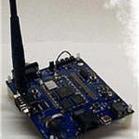
DVK-WLM400 Laird Technologies, DVK-WLM400 Datasheet - Page 10

DVK-WLM400
Manufacturer Part Number
DVK-WLM400
Description
DEVELOPMENT KIT WISM+
Manufacturer
Laird Technologies
Type
Transceiverr
Datasheet
1.DVK-WLM400.pdf
(43 pages)
Specifications of DVK-WLM400
Frequency
2.4GHz
Processor Series
WISM+
Silicon Manufacturer
Laird Technologies
Kit Application Type
Communication & Networking
Application Sub Type
Wi-Fi Intelligent Serial
Kit Contents
PCB, 2x Antennas, Power Adapter, USB Cable, RS-232
Rohs Compliant
Yes
For Use With/related Products
WLM400
Lead Free Status / RoHS Status
Lead free / RoHS Compliant
Lead Free Status / RoHS Status
Lead free / RoHS Compliant, Lead free / RoHS Compliant
The host com port can be used for the following things…
2.2.2
This is the host communications SPI interface to the WISM+. This is a dual-row 10 pin male header which mates with
the Ardvark USB to SPI module http://www.totalphase.com/products/aardvark_i2cspi/. If you purchase this device,
and load the drivers, WIF.exe can be configured to operate over the SPI port. The following table indicates the pin out
of the SPI header…
Pin 1 is the lower left pin. The bottom row of pins are numbered 1,3,5…etc (with even pin numbers on top).
SPI Header
•
•
•
© Laird Technology 2010
PIN#
10
HyperTerminal can be used on a PC to send AT commands to the WISM+ and display responses.
WIF.exe can be configured to operate over host com port after an “at+quit”.
The entire WAPI command interface can be implemented over the host com port after an “at+quit”.
1
2
3
4
5
6
7
8
9
SPI Header
GND
RESERVED
N/C
SPI_MISO
N/C
SPI_CLK
SPI_MOSI
GND
SPI Header
PIN NAME
SPI_REQ
SPI_SS
I/O
O
O
I
I
I
WISM+
PIN #
19
28
30
29
31
SPI_MISO
SPI_CLK
SPI_MOSI
PIN NAME
SPI_REQ
SPI_SS
WISM+
DESCRIPTION
This is an output from the WISM+ which is
asserted (low) when the WISM+ has data to be
transferred back to the host.
Ground pin connected to the ground plane of the
Dev Kit PCB.
This pin does go to a WISM+ port pin, but has no
function.
This pin is not connected
This is the MISO (Master In Slave Out) data line
for the SPI interface. This should be connected
to the MISO of a SPI Master device.
This pin is not connected
This is the clock input for the SPI interface. This
is an input to the WISM+ because the WISM+ is
always a SPI SLAVE device, intended to be
connected to the clock output of a SPI Master
device.
This is the MOSI (Master Out Slave In) data line
for the SPI interface. This should be connected
to the MOSI of a SPI Master device.
This is the SPI Slave Select input to the WISM+.
This is driven low by a SPI Master device to
frame the data transfer.
Ground pin connected to the ground plane of the
Dev Kit PCB.
Version 1.00
WISM+ DVK MANUAL
Page 5


