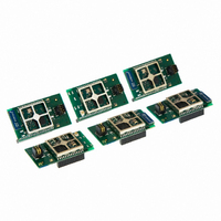
EM35X-DEV Ember, EM35X-DEV Datasheet - Page 152

EM35X-DEV
Manufacturer Part Number
EM35X-DEV
Description
KIT DEV EM35X ZIGBEE
Manufacturer
Ember
Series
EM35xr
Type
Transceiver, 802.15.4r
Specifications of EM35X-DEV
Frequency
2.4GHz
For Use With/related Products
EM351, EM357
Lead Free Status / RoHS Status
Lead free / RoHS Compliant
Other names
636-1012
- Current page: 152 of 245
- Download datasheet (12Mb)
9.3.14.4
This example sets the enable of Timer 1 when its TI1 input rises, and the enable of Timer 2 with the enable of
Timer 1. To ensure the counters are aligned, Timer 1 must be configured in master/slave mode (slave with
respect to TI1, master with respect to Timer 2):
When a rising edge occurs on TI1 (Timer 1), both counters start counting synchronously on the internal clock
and both timers’ INT_TIMTIF flags are set. Figure 9-36 shows this in operation.
Note: In this example both timers are initialized before starting by setting their respective TIM_UG bits. Both
counters starts from 0, but an offset can be inserted between them by writing any of the counter registers
(TIMx_CNT). The master/slave mode inserts a delay between CNT_EN and CK_PSC on Timer 1.
Configure Timer 1 in master mode to send its Enable as trigger output: Write TIM_MMS = 001 in the
TIM1_CR2 register.
Configure Timer 1 slave mode to get the input trigger from TI1: Write TIM_TS = 100 in the TIM1_SMCR
register.
Configure Timer 1 in trigger mode: Write TIM_SMS = 110 in the TIM1_SMCR register.
Configure the Timer 1 in master/slave mode: Write TIM_MSM = 1 in the TIM1_SMCR register.
Configure Timer 2 to get the input trigger from Timer 1: Write TIM_TS = 000 in the TIM2_SMCR register.
Configure Timer 2 in trigger mode: Write TIM_SMS = 110 in the TIM2_SMCR register.
Starting both Timers Synchronously in Response to an External Trigger
Figure 9-35. Triggering Timer 2 with Enable of Timer 1
Final
9-28
120-035X-000G
Related parts for EM35X-DEV
Image
Part Number
Description
Manufacturer
Datasheet
Request
R

Part Number:
Description:
EM35X ADD ON KIT
Manufacturer:
Ember
Datasheet:

Part Number:
Description:
KIT DEV EM35X IAR EWARM ZIGBEE
Manufacturer:
Ember
Datasheet:

Part Number:
Description:
EM35X BREAKOUT BOARD
Manufacturer:
Ember
Datasheet:

Part Number:
Description:
IAR EWARM LICENCE FOR EM35X
Manufacturer:
Ember
Datasheet:

Part Number:
Description:
KIT DEV EMBER ZIGBEE W/PCWH
Manufacturer:
Custom Computer Services Inc (CCS)

Part Number:
Description:
PROGRAMMER USB FLASH EM250/260
Manufacturer:
Ember
Datasheet:

Part Number:
Description:
IC ZIGBEE SYSTEM-ON-CHIP 40-QFN
Manufacturer:
Ember
Datasheet:

Part Number:
Description:
IC ZIGBEE SYSTEM-ON-CHIP 48-QFN
Manufacturer:
Ember
Datasheet:

Part Number:
Description:
IC RF TXRX ZIGBEE 128KB 48QFN
Manufacturer:
Ember
Datasheet:

Part Number:
Description:
IC RF TXRX ZIGBEE 192KB 48QFN
Manufacturer:
Ember
Datasheet:

Part Number:
Description:
INSIGHT ADAPTER FOR EM2XX
Manufacturer:
Ember
Datasheet:

Part Number:
Description:
KIT EVAL EM250 RF TEST
Manufacturer:
Ember
Datasheet:

Part Number:
Description:
INSIGHT ADAPTER 3 FOR EM35X
Manufacturer:
Ember
Datasheet:

Part Number:
Description:
EM250 RCM BOARD
Manufacturer:
Ember
Datasheet:

Part Number:
Description:
EM260 RCM BOARD
Manufacturer:
Ember
Datasheet:


