ATMEGA64RZAV-10PU Atmel, ATMEGA64RZAV-10PU Datasheet - Page 32
ATMEGA64RZAV-10PU
Manufacturer Part Number
ATMEGA64RZAV-10PU
Description
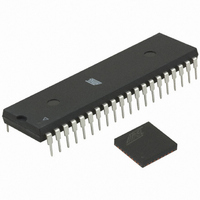
MCU ATMEGA644/AT86RF230 40-DIP
Manufacturer
Atmel
Series
ATMEGAr
Datasheets
1.ATMEGA644-20MU.pdf
(23 pages)
2.ATMEGA644-20MU.pdf
(376 pages)
3.AT86RF230-ZU.pdf
(98 pages)
Specifications of ATMEGA64RZAV-10PU
Frequency
2.4GHz
Modulation Or Protocol
802.15.4 Zigbee
Power - Output
3dBm
Sensitivity
-101dBm
Voltage - Supply
1.8 V ~ 3.6 V
Data Interface
PCB, Surface Mount
Memory Size
64kB Flash, 2kB EEPROM, 4kB RAM
Antenna Connector
PCB, Surface Mount
Package / Case
40-DIP (0.600", 15.24mm)
Wireless Frequency
2.4 GHz
Interface Type
JTAG, SPI
Output Power
3 dBm
For Use With
ATSTK600-TQFP32 - STK600 SOCKET/ADAPTER 32-TQFPATAVRISP2 - PROGRAMMER AVR IN SYSTEMATSTK500 - PROGRAMMER AVR STARTER KIT
Lead Free Status / RoHS Status
Lead free / RoHS Compliant
Operating Temperature
-
Applications
-
Data Rate - Maximum
-
Current - Transmitting
-
Current - Receiving
-
Lead Free Status / Rohs Status
Lead free / RoHS Compliant
For Use With/related Products
ATmega64


7.2.2 Configuration
32
AT86RF230
RX_AACK:
The state RX_AACK_ON is entered by writing the command RX_AACK_ON to the
register bits TRX_CMD in register 0x02 (TRX_STATE). The state change shall be
confirmed by reading register 0x01 (TRX_STATUS) that changes to RX_AACK_ON or
BUSY_RX_AACK on success.
TX_ARET:
Similarly, TX_ARET_ON state is activated by setting register bits TRX_CMD (register
0x02) to TX_ARET_ON. The radio transceiver is in the TX_ARET_ON state after
TRX_STATUS (register 0x01) has changed to TX_ARET_ON.
Notes:
1. It is not recommended to use the FORCE_TRX_OFF command while being in state
2. After state transition from state RX_AACK_ON to state PLL_ON, start of frame
The use of the Extended Operating Mode is based on Basic Operating Mode
functionality. Only features beyond the basic radio transceiver functionality are
described in the following sections. For details to the Basic Operating Mode refer to
section 7.1.
When using the RX_AACK or TX_ARET modes, the following registers needs to be
configured.
RX_AACK:
• Setup registers 0x20 – 0x2B for PAN-ID and IEEE addresses
• Set register bit AACK_SET_PD (register 0x2E)
• Configure register bit I_AM_COORD (register 0x2E)
TX_ARET:
• Configure CSMA-CA
• Configure CCA (see section 8.7)
The MIN_BE register bits (register 0x2E) sets the minimum back-off exponent (refer to
IEEE 802.15.4-2003 section 7.5.1.3), and the CSMA_SEED_0 and CSMA_SEED_1
register bits (registers 0x2D, 0x2E) define a random seed for the back-off-time random-
number generator in the AT86RF230. The register bits MAX_CSMA_RETRIES (register
0x2C) configures how often the radio transceiver retries the CSMA-CA algorithm after a
busy channel is detected. MAX_FRAME_RETRIES (register 0x2C) defines the
maximum number of frame retransmissions.
BUSY_TX_ARET without appending a SLEEP cycle by activating SLP_TR for at
least 2 µs.
transmission shall be confirmed by reading register 0x01 (TRX_STATUS). If register
bits TRX_STATUS do not return BUSY_TX during frame transmission, the frame
transmission needs to be initiated again. If the frame has been downloaded before
initiating the frame transmission, it has to be downloaded again.
-
-
-
-
MAX_FRAME_RETRIES (register 0x2C)
MAX_CSMA_RETRIES (register 0x2C)
CSMA_SEED (registers 0x2D, 0x2E)
MIN_BE (register 0x2E)
5131E-MCU Wireless-02/09
Related parts for ATMEGA64RZAV-10PU
Image
Part Number
Description
Manufacturer
Datasheet
Request
R

Part Number:
Description:
DEV KIT FOR AVR/AVR32
Manufacturer:
Atmel
Datasheet:

Part Number:
Description:
INTERVAL AND WIPE/WASH WIPER CONTROL IC WITH DELAY
Manufacturer:
ATMEL Corporation
Datasheet:
Part Number:
Description:
Low-Voltage Voice-Switched IC for Hands-Free Operation
Manufacturer:
ATMEL Corporation
Datasheet:
Part Number:
Description:
MONOLITHIC INTEGRATED FEATUREPHONE CIRCUIT
Manufacturer:
ATMEL Corporation
Datasheet:
Part Number:
Description:
AM-FM Receiver IC U4255BM-M
Manufacturer:
ATMEL Corporation
Datasheet:
Part Number:
Description:
Monolithic Integrated Feature Phone Circuit
Manufacturer:
ATMEL Corporation
Datasheet:
Part Number:
Description:
Multistandard Video-IF and Quasi Parallel Sound Processing
Manufacturer:
ATMEL Corporation
Datasheet:
Part Number:
Description:
High-performance EE PLD
Manufacturer:
ATMEL Corporation
Datasheet:
Part Number:
Description:
8-bit Flash Microcontroller
Manufacturer:
ATMEL Corporation
Datasheet:
Part Number:
Description:
2-Wire Serial EEPROM
Manufacturer:
ATMEL Corporation
Datasheet: