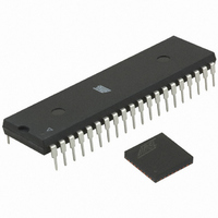
ATMEGA64RZAV-10PU Atmel, ATMEGA64RZAV-10PU Datasheet - Page 48

ATMEGA64RZAV-10PU
Manufacturer Part Number
ATMEGA64RZAV-10PU
Description
MCU ATMEGA644/AT86RF230 40-DIP
Manufacturer
Atmel
Series
ATMEGAr
Datasheets
1.ATMEGA644-20MU.pdf
(23 pages)
2.ATMEGA644-20MU.pdf
(376 pages)
3.AT86RF230-ZU.pdf
(98 pages)
Specifications of ATMEGA64RZAV-10PU
Frequency
2.4GHz
Modulation Or Protocol
802.15.4 Zigbee
Power - Output
3dBm
Sensitivity
-101dBm
Voltage - Supply
1.8 V ~ 3.6 V
Data Interface
PCB, Surface Mount
Memory Size
64kB Flash, 2kB EEPROM, 4kB RAM
Antenna Connector
PCB, Surface Mount
Package / Case
40-DIP (0.600", 15.24mm)
Wireless Frequency
2.4 GHz
Interface Type
JTAG, SPI
Output Power
3 dBm
For Use With
ATSTK600-TQFP32 - STK600 SOCKET/ADAPTER 32-TQFPATAVRISP2 - PROGRAMMER AVR IN SYSTEMATSTK500 - PROGRAMMER AVR STARTER KIT
Lead Free Status / RoHS Status
Lead free / RoHS Compliant
Operating Temperature
-
Applications
-
Data Rate - Maximum
-
Current - Transmitting
-
Current - Receiving
-
Lead Free Status / Rohs Status
Lead free / RoHS Compliant
For Use With/related Products
ATmega64
8.1.2.6 MAC Footer (MFR) Fields
8.2 Frame Check Sequence (FCS)
8.2.1.1 Overview
8.2.2 CRC calculation
48
AT86RF230
The MAC footer consists of a two-octet frame checksum (FCS). The AT86RF230 can
generate and evaluate this FCS automatically, for details refer to section 8.2.
The frame check sequence main features are:
• Indicates bit errors, based on a cyclic redundancy check (CRC) of length 16 bit
• Uses International Telecommunication Union (ITU) CRC polynomial
• Automatically evaluated during reception
• Can be automatically generated during transmission
The FCS is intended for use at the MAC level to detect corrupted frames. It is computed
by applying an ITU CRC polynomial to all transferred bytes following the length field
(MHR and MSDU fields). The frame check sequence has a length of 16 bit and is
located in the last two bytes of a frame (MAC footer, see Figure 8-2).
The AT86RF230 applies an FCS check on each received frame. The FCS check result
is stored to register bit RX_CRC_VALID in register 0x06 (PHY_RSSI). On transmit the
radio transceiver can be configured to autonomously compute and append the FCS
bytes.
The CRC polynomial used in IEEE 802.15.4-2003 networks is defined by
The FCS shall be calculated for transmission using the following algorithm:
Let
be the polynomial representing the sequence of bits for which the checksum is to be
computed. Multiply M(x) by x
Divide N(x) modulo 2 by the generator polynomial, G
polynomial,
The FCS field is given by the coefficients of the remainder polynomial, R(x) .
Example:
Considering a 5 octet ACK frame. The MHR field consists of
The leftmost bit (b
The leftmost bit (r
0100 0000 0000 0000 0101 0110.
0010 0111 1001 1110.
G
M
R
N
16
(
(
(
x
(
x
x
)
x
)
)
)
=
=
=
=
M
b
r
0
0
0
) is transmitted first in time.
x
0
) is transmitted first in time. The FCS would be following
x
(
16
x
15
x
k
)
−
+
+
1
⋅
x
x
+
x r
16
1
12
b
.
1
14
+
x
16
k
+
, giving the polynomial
x
−
5
2
...
+
+
+
1
K
r
.
14
+
x
b
+
k
−
r
15
2
x
+
b
k
−
1
16
(x) , to obtain the remainder
5131E-MCU Wireless-02/09


