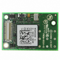
WISMC03BI Laird Technologies, WISMC03BI Datasheet - Page 9

WISMC03BI
Manufacturer Part Number
WISMC03BI
Description
MODULE LAN 802.11B/G BISM
Manufacturer
Laird Technologies
Series
EZURiOr
Specifications of WISMC03BI
Frequency
2.4GHz
Data Rate - Maximum
1Mbps
Modulation Or Protocol
802.11 b/g
Applications
AMR, Automotive, ISM
Power - Output
15dBm
Sensitivity
-86dBm
Voltage - Supply
3.3 V ~ 5.5 V
Current - Transmitting
250mA
Data Interface
Connector, 50 Pin, DF-12
Memory Size
64Mbyte Flash, 16MByte SRAM
Antenna Connector
U.FL
Operating Temperature
-40°C ~ 85°C
Package / Case
Module
Wireless Frequency
2.412 GHz to 2.484 GHz
Interface Type
UART
Board Size
22.8 mm x 33.8 mm x 7.6 mm
Modulation
BPSK, CCK, DSSS, QPSK
Security
WEP 64/128, WPA-PSK, WPA2, TKIP, AES-CCMP
Lead Free Status / RoHS Status
Lead free / RoHS Compliant
Current - Receiving
-
Lead Free Status / Rohs Status
Lead free / RoHS Compliant
WISMC03BI
Wireless LAN Module / Device Server
ELECTRICAL
SPECIFICATIONS
9
www.lairdtech.com
40 WAY HIROSE PIN DESCRIPTIONS
The Hirose DF12C board-to-board connector on the module is a 40-pin double-row receptacle.
The table below defines the pin functions. The pin-out is as viewed from the underside of the Module.
Notes:
The reset circuitry within the module incorporates a brown-out detector. The reset pin has a fixed 10kOhm pull down
resistor to ground, followed by a 10kOhm resistor feeding the base of a transistor.
GPIO lines can be configured through software to be either inputs or outputs. At reset, all GPIO lines, other than those
that have dual functionality as modem control signals are configured as inputs.
UART_RX, UART_TX, UART_CTS, UART_RTS, UART_RI, UART_DCD, UART_DTR and UART_DSR are all 3.0v level logic.
When the signal sits at 3.0V it is de-asserted. When the signal is at 0V it is asserted.
UART_RX, UART_TX, UART_CTS, UART_RTS are controlled directly by the module. The operation of UART_RI, UART_DCD
and UART_DTR is user programmable.
Pin 27 (VCC_3V) may only be used for monitoring purposes. It must not be used as a current source.
Pin 22 (WAKEUP) will be used for future powersave functionality. It has an internal 100kOhm pull-up.
ADC inputs (pins 1 and 3) are read using commands over the UART.
UART_DSR is used to signal the module to enter Power Save Mode 2.
Pins marked N/C may have internal connections within the module and should not be connected to any external circuitry.
PIN
10
11
12
13
14
15
16
17
18
19
20
21
22
23
24
25
26
27
28
29
30
31
32
33
34
35
36
37
38
39
40
1
2
3
4
5
6
7
8
9
SIGNAL
ADC 0
GPIO1
ADC 1
GPIO2
WLAN_ACTIVE
UART_RI
N/C
UART_DCD
N/C
UART_DSR
GND
UART_DTR
RESET
GPIO4
GND
GPIO5
N/C
GND
UART_CTS
N/C
UART_TX
WAKEUP
UART_RTS
BT_PRIORITY
UART_RX
N/C
VCC_3V
VCC_5V
VCC_5V
GND
VCC_5V
N/C
GPIO6
N/C
GPIO7
GND
GPIO8
GND
GPIO9
BT_STATE
DESCRIPTION
3.0 V Max
I/O for Host.
3.0 V Max
I/O for Host
Output
RING or GPIO12
DCD or GPIO13
DSR or GPIO10
DTR or GPIO11
Reset Input
I/O for Host
I/O for Host
Clear to Send Input
Transmit Data Output
Reserved
Request to Send Output
Input
Receive Data Input
3.0V Monitor
Supply
Supply
Supply
I/O for Host
I/O for Host
I/O for Host
I/O for Host
Input
Laird Technologies


