IXEN60N120 IXYS, IXEN60N120 Datasheet - Page 2
IXEN60N120
Manufacturer Part Number
IXEN60N120
Description
IGBT NPT3 1200V 100A SOT-227B
Manufacturer
IXYS
Datasheet
1.IXEN60N120D1.pdf
(4 pages)
Specifications of IXEN60N120
Igbt Type
NPT
Configuration
Single
Voltage - Collector Emitter Breakdown (max)
1200V
Vce(on) (max) @ Vge, Ic
2.7V @ 15V, 60A
Current - Collector (ic) (max)
100A
Current - Collector Cutoff (max)
800µA
Input Capacitance (cies) @ Vce
3.8nF @ 25V
Power - Max
445W
Input
Standard
Ntc Thermistor
No
Mounting Type
Chassis Mount
Package / Case
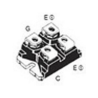
SOT-227, miniBLOC
Channel Type
N
Collector-emitter Voltage
1.2kV
Collector Current (dc) (max)
100A
Gate To Emitter Voltage (max)
±20V
Package Type
SOT-227B
Pin Count
4
Mounting
Screw
Operating Temperature (min)
-40C
Operating Temperature (max)
150C
Operating Temperature Classification
Automotive
Vces, (v)
1200
Ic25, Tc=25°c, Igbt, (a)
100
Ic90, Tc=90°c, Igbt, (a)
65
Vce(sat), Max, Tj=25°c, Igbt, (v)
2.7
Tfi, Typ, Igbt, (ns)
30
Eoff, Typ, Tj=125°c, Igbt, (mj)
4.8
Rthjc, Max, Igbt, (°c/w)
0.28
If, Tc=90°c, Diode, (a)
-
Rthjc, Max, Diode, (k/w)
-
Package Style
SOT-227B
Lead Free Status / RoHS Status
Lead free / RoHS Compliant


Symbol
I
I
Symbol
V
I
t
R
Symbol
T
T
V
M
Symbol
R
Weight
© 2003 IXYS All rights reserved
Diode (D1 version only)
F25
F90
RM
Component
rr
VJ
stg
F
ISOL
thJC
thCH
D
Conditions
T
T
Conditions
I
I
I
V
Conditions
I
mounting torque
teminal connection torque
Conditions
with heatsink compound
F
F
F
ISOL
C
C
GE
= 60 A, V
= 60 A, V
= 60 A, -di
= 25°C
= 90°C
= 0 V, T
≤ 1 mA; 50/60 Hz
GE
GE
J
F
/dt = 500 A/µs, V
= 125°C
= 0 V
= 0 V, T
J
= 125°C
(T
R
(M4)
(M4)
miniBLOC, SOT-227 B
= 600 V
J
M4 screws (4x) supplied
= 25°C, unless otherwise specified)
min.
min.
Characteristic Values
Characteristic Values
-40...+150
-40...+150
Maximum Ratings
Maximum Ratings
200
typ.
2.3
1.7
41
typ.
0.1
30
2500
1.5
1.5
max.
110
max.
2.7
0.6 K/W
60
Nm
Nm
K/W
V~
°C
°C
ns
A
A
V
V
A
g
Conduction
IGBT (typ. at V
Diode (typ. at T
Thermal Response
IGBT (typ.)
Diode (typ.)
Equivalent Circuits for Simulation
Dim.
A
B
C
D
E
F
G
H
J
K
L
M
N
O
P
Q
R
S
T
U
V
W
C
C
C
C
th1
th2
th1
th2
V
31.50
14.91
30.12
37.80
11.68
12.60
25.15
26.54
24.59
0.780
-0.05
= 0.14 J/K; R
= 0.91 J/K; R
= 0.08 J/K; R
= 0.54 J/K; R
Min.
V
7.80
4.09
4.09
4.09
8.92
0.76
1.98
4.95
3.94
4.72
3.30
0
IXEN 60N120
IXEN 60N120D1
0
= 0.99 V; R
Millimeter
= 1.3 V; R
GE
J
= 125°C)
= 15 V; T
31.88
15.11
30.30
38.20
12.22
12.85
25.42
26.90
25.07
0.830
Max.
8.20
4.29
4.29
4.29
9.60
0.84
2.13
5.97
4.42
4.85
4.57
0.1
th1
th2
th1
th2
0
0
= 7 m Ω
= 25 m Ω
= 0.20 K/W
= 0.08 K/W
= 0.45 K/W
= 0.15 K/W
-0.002
1.240
0.307
0.161
0.161
0.161
0.587
1.186
1.489
0.460
0.351
0.030
0.496
0.990
0.078
0.195
1.045
0.155
0.186
0.968
0.130
19.81
J
Min.
= 125°C)
Inches
1.255
0.323
0.169
0.169
0.169
0.595
1.193
1.505
0.481
0.378
0.033
0.506
1.001
0.084
0.235
1.059
0.174
0.191
0.987
0.004
0.180
21.08
Max.
2 - 4
Related parts for IXEN60N120
Image
Part Number
Description
Manufacturer
Datasheet
Request
R


Part Number:
Description:
HiPerFET Power MOSFETs
Manufacturer:
IXYS Corporation
Datasheet:
Part Number:
Description:
J-K-Type Flip-Flop
Manufacturer:
IXYS Corporation
Datasheet:
Part Number:
Description:
HiPerRF Power MOSFETs
Manufacturer:
IXYS Corporation
Datasheet:
Part Number:
Description:
Rectifier Module for Three Phase Power Factor Correction
Manufacturer:
IXYS Corporation
Datasheet:
Part Number:
Description:
Thyristor Modules Thyristor/Diode Modules
Manufacturer:
IXYS Corporation
Datasheet:
Part Number:
Description:
Thyristor Modules Thyristor/Diode Modules
Manufacturer:
IXYS Corporation
Datasheet:
Part Number:
Description:
Thyristor Modules Thyristor/Diode Modules
Manufacturer:
IXYS Corporation
Datasheet:
Part Number:
Description:
Thyristor Modules Thyristor/Diode Modules
Manufacturer:
IXYS Corporation
Datasheet:
Part Number:
Description:
Thyristor Modules /Diode Modules
Manufacturer:
IXYS Corporation
Datasheet:
Part Number:
Description:
Thyristor Modules /Diode Modules
Manufacturer:
IXYS Corporation
Datasheet:
Part Number:
Description:
Thyristor Modules Thyristor/Diode Modules
Manufacturer:
IXYS Corporation
Datasheet: