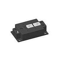
VMO1200-01F IXYS, VMO1200-01F Datasheet - Page 6

VMO1200-01F
Manufacturer Part Number
VMO1200-01F
Description
MOSFET N-CH 100V 1245A Y3-LI
Manufacturer
IXYS
Series
HiPerFET™r
Type
Single Switch MOSFETs Moduler
Datasheet
1.VMO1200-01F.pdf
(6 pages)
Specifications of VMO1200-01F
Fet Type
MOSFET N-Channel, Metal Oxide
Fet Feature
Standard
Rds On (max) @ Id, Vgs
1.35 mOhm @ 932A, 10V
Drain To Source Voltage (vdss)
100V
Current - Continuous Drain (id) @ 25° C
1245A
Vgs(th) (max) @ Id
4V @ 64mA
Gate Charge (qg) @ Vgs
2520nC @ 10V
Mounting Type
Chassis Mount
Package / Case
Y3-Li
Mounting Style
Screw
Product
Power Semiconductor Modules
Typical Delay Time
360 ns
Vdss, Max, (v)
100
Id25, Tc = 25°c, (a)
1220
Id80, Tc = 80°c, (a)
970
Rds(on), Max, Tj = 25°c, (mohms)
1.25
Tf, Typ, (ns)
1020
Tr, Typ, (ns)
1620
Rthjc, Max, (k/w)
0.053
Package Style
Y3-Li (w/o terminal 1, low inductance)
Lead Free Status / RoHS Status
Lead free / RoHS Compliant
Power - Max
-
Lead Free Status / Rohs Status
Lead free / RoHS Compliant
© 2010 IXYS All rights reserved
[A]
I
[A]
RM
I
S
1000
120
100
800
600
400
200
80
60
40
20
V
V
I
0
D
GS
DS
200
0.0
Fig. 13 Typ. reverse recovery current I
Fig. 15 Source drain current I
Fig. 17 Definition of switching times
0.1 I
0.1 V
V
I
T
t
D
d(on)
VJ
R
= 1000 A
0.2
= 50 V
= 25°C
D
300
0.9 I
GS
typical source drain voltage V
of the body diode versus di/dt
t
r
D
0.4
400
di
F
V
/dt [A/µs]
SD
0.6
[V]
500
0.8
F
(body diode) vs.
600
1.0
0.9 V
SD
RM
t
d(off)
GS
700
1.2
0.9 I
t
f
0.1 I
D
D
t
t
[K/W]
R
thJH
[µC]
Q
rr
0.07
0.06
0.05
0.04
0.03
0.02
0.01
0.00
24
22
20
18
16
14
12
10
8
6
4
200
1
Fig. 14 Typical reverse recovery charge Q
Fig. 16 Typ. transient thermal impedance
V
I
T
D
VJ
R
= 1000 A
= 50 V
= 25°C
300
of the body diode versus di/dt
with heat tranfer paste (IXYS test setup)
10
400
di
F
t [ms]
VMO 1200-01F
/dt [A/µs]
100
500
1000
600
10000
20100614b
700
rr
6 - 6


