SCP1000 PCB3 VTI Technologies, SCP1000 PCB3 Datasheet - Page 23
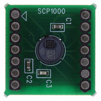
SCP1000 PCB3
Manufacturer Part Number
SCP1000 PCB3
Description
SENSOR I2C 30-120KPA PCB
Manufacturer
VTI Technologies
Series
SCP1000r
Datasheet
1.SCP1000_PCB3.pdf
(37 pages)
Specifications of SCP1000 PCB3
Pressure Type
Absolute
Operating Pressure
4.35 ~ 17.40 PSI, 30 ~ 120 kPa
Output
Digital
Voltage - Supply
2.4 V ~ 3.3 V
Termination Style
Surface Mount
Operating Temperature
-20°C ~ 70°C
Package / Case
PCB Mount
Lead Free Status / RoHS Status
Lead free / RoHS Compliant
Other names
551-1044


4
4.1 SPI Interface
4.1.1
VTI Technologies Oy
www.vti.fi
Serial Interfaces
SPI frame format
Communication between SCP1000 sensor and master controller is based on serial data transfer
and dedicated interrupt line (DRDY-pin). Depending on operation mode an external trigger pin
(TRIG) can also be used in serial interfacing. Two different serial interfaces are available for
SCP1000 sensor: SPI and TWI (very similar to I
enabled by pre-programming in the factory. SCP1000 acts as a slave on both SPI and TWI bus.
The SPI interface is a full duplex 4 wire serial interface. The connection between the µC and
SCP1000 is done using MOSI, MISO, SCK and CSB. CSB selects the chip on multi-chip SPI bus,
SCK is the serial data clock, MOSI is the data line from master to slave (Master Out Slave In) and
MISO is data line from slave to master (Master In Slave Out). SCP1000 is configured to SPI slave
mode (see Figure 8).
The SCP1000 SPI frame format is presented in Figure 9 below.
Figure 9. SPI frame format for two 8 bit words.
Each SPI communication frame contains two or three 8 bit words: the first word defines the register
address (6 bits wide, bits [A5:A0] in Figure 9) followed by the type of access (‘0’ = Read or
‘1’ = Write) and one zero bit (bit 0, LSB). The following word(s) contain the data being read or
written. The MSB of the words are sent first. Bits from MOSI line are sampled in on the rising edge
of SCK and bits to MISO line are latched out on falling edge of SCK.
The CSB line must stay low during the entire frame accesses, i.e. between the bytes. If the CSB
line state changes to high, the access is terminated. The CSB has to be pulled up after each
communication frame.
Figure 8. SPI master slave configuration.
Master µC
Doc.Nr. 8260800.08
Subject to changes
2
SCP1000
C). However, only one interface per product is
SCP1000 Series
Rev.0.08
23/37
Related parts for SCP1000 PCB3
Image
Part Number
Description
Manufacturer
Datasheet
Request
R


Part Number:
Description:
SENSOR 30-120KPA SPI
Manufacturer:
VTI Technologies
Datasheet:

Part Number:
Description:
SENSOR SPI 30-120KPA PCB
Manufacturer:
VTI Technologies
Datasheet:

Part Number:
Description:
SENSOR I2C 30-120KPA
Manufacturer:
VTI Technologies
Datasheet:

Part Number:
Description:
ACCELEROMETER SGL 1.7G DIL8 SMD
Manufacturer:
VTI Technologies
Datasheet:

Part Number:
Description:
VTI Automotive Digital Accelerometer Platform
Manufacturer:
VTI [VTI technologies]
Datasheet:

Part Number:
Description:
BOARD PWB ACCEL 3-AXIS SPI/I2C
Manufacturer:
VTI Technologies
Datasheet:

Part Number:
Description:
EVAL BOARD ACCELEROMETER Y-AXIS
Manufacturer:
VTI Technologies
Datasheet:

Part Number:
Description:
EVAL BOARD INCLINOMETER Y-AXIS
Manufacturer:
VTI Technologies
Datasheet:

Part Number:
Description:
KIT DEMO ACCELEROMTR CMA3000-D01
Manufacturer:
VTI Technologies
Datasheet:
Part Number:
Description:
ACCELEROMETER SGL 1.7G DIL8 SMD
Manufacturer:
VTI Technologies
Datasheet:
Part Number:
Description:
VTI Automotive Digital Accelerometer Platform
Manufacturer:
VTI [VTI technologies]
Datasheet:
Part Number:
Description:
Accelerometer
Manufacturer:
VTI [VTI technologies]
Datasheet:
Part Number:
Description:
Stand Alone Inclinometer
Manufacturer:
VTI [VTI technologies]
Datasheet:
Part Number:
Description:
3-axis accelerometer
Manufacturer:
VTI [VTI technologies]
Datasheet: