SCP1000 PCB3 VTI Technologies, SCP1000 PCB3 Datasheet - Page 26
SCP1000 PCB3
Manufacturer Part Number
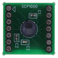
SCP1000 PCB3
Description
SENSOR I2C 30-120KPA PCB
Manufacturer
VTI Technologies
Series
SCP1000r
Datasheet
1.SCP1000_PCB3.pdf
(37 pages)
Specifications of SCP1000 PCB3
Pressure Type
Absolute
Operating Pressure
4.35 ~ 17.40 PSI, 30 ~ 120 kPa
Output
Digital
Voltage - Supply
2.4 V ~ 3.3 V
Termination Style
Surface Mount
Operating Temperature
-20°C ~ 70°C
Package / Case
PCB Mount
Lead Free Status / RoHS Status
Lead free / RoHS Compliant
Other names
551-1044


4.2.1.1
VTI Technologies Oy
www.vti.fi
TWI write sequence
8 bit TWI write sequence is presented in Figure 13 and described below:
Figure 13. TWI frame format for 8 bit write operation (numbers from 1 to 8 refer to list above).
1. START BIT (to initiate a transmission, the master sends a start bit)
2. SLAVE DEVICE ADDRESS (slave device address with WRITE access → LSB = ‘0’)
3. SLAVE ACKNOWLEDGEMENT (having identified device address as its own, slave
4. REGISTER ADDRESS (the 8 bit address of the register to be written, MSB first)
5. SLAVE ACKNOWLEDGEMENT (the slave sends an acknowledgement bit)
6. REGISTER DATA (master sends the data to be written to the addressed register)
7. SLAVE ACKNOWLEDGEMENT (after receiving the byte, the slave sends an
8. STOP BIT (master sets the bus free)
1.
acknowledges by sending an acknowledge bit)
acknowledgement bit)
REGISTER ADDRESS (µC → SCP1000)
Master sends register address to SCP1000 MSB first.
REGISTER DATA (SCP1000 → µC)
The SCP1000 registers can be 8 or 16 bits wide. An 8 bit write is performed by
sending MSB first. A 16 bits write is performed by sending two bytes (MSB first).
After each byte, the slave sends an acknowledgement bit.
STOP BIT (µC → SCP1000)
The stop bit is a low to high transition on SDA, while SCL is high. The master, who
has generated the stop bit, sets the bus free.
REPEATED START (µC → SCP1000)
A repeated start is a start signal generated by a master, which has already taken the
control of the TWI bus. It is used by the master to initiate a transfer with a new slave,
or with the same slave, in the other communication mode (transmit or receive mode),
without releasing the bus.
NOT ACKNOWLEGDE BIT:
If the receiver of the acknowledge bit reads a ‘1’ on SDA line during an acknowledge
clock pulse, that means transmitter did not acknowledge. The master uses the not
acknowledge bit to terminate a read action.
2.
3.
Doc.Nr. 8260800.08
Subject to changes
4.
5.
6.
SCP1000 Series
7.
Rev.0.08
26/37
8.
Related parts for SCP1000 PCB3
Image
Part Number
Description
Manufacturer
Datasheet
Request
R


Part Number:
Description:
SENSOR 30-120KPA SPI
Manufacturer:
VTI Technologies
Datasheet:

Part Number:
Description:
SENSOR SPI 30-120KPA PCB
Manufacturer:
VTI Technologies
Datasheet:

Part Number:
Description:
SENSOR I2C 30-120KPA
Manufacturer:
VTI Technologies
Datasheet:

Part Number:
Description:
ACCELEROMETER SGL 1.7G DIL8 SMD
Manufacturer:
VTI Technologies
Datasheet:

Part Number:
Description:
VTI Automotive Digital Accelerometer Platform
Manufacturer:
VTI [VTI technologies]
Datasheet:

Part Number:
Description:
BOARD PWB ACCEL 3-AXIS SPI/I2C
Manufacturer:
VTI Technologies
Datasheet:

Part Number:
Description:
EVAL BOARD ACCELEROMETER Y-AXIS
Manufacturer:
VTI Technologies
Datasheet:

Part Number:
Description:
EVAL BOARD INCLINOMETER Y-AXIS
Manufacturer:
VTI Technologies
Datasheet:

Part Number:
Description:
KIT DEMO ACCELEROMTR CMA3000-D01
Manufacturer:
VTI Technologies
Datasheet:
Part Number:
Description:
ACCELEROMETER SGL 1.7G DIL8 SMD
Manufacturer:
VTI Technologies
Datasheet:
Part Number:
Description:
VTI Automotive Digital Accelerometer Platform
Manufacturer:
VTI [VTI technologies]
Datasheet:
Part Number:
Description:
Accelerometer
Manufacturer:
VTI [VTI technologies]
Datasheet:
Part Number:
Description:
Stand Alone Inclinometer
Manufacturer:
VTI [VTI technologies]
Datasheet:
Part Number:
Description:
3-axis accelerometer
Manufacturer:
VTI [VTI technologies]
Datasheet: