SCP1000 PCB3 VTI Technologies, SCP1000 PCB3 Datasheet - Page 9
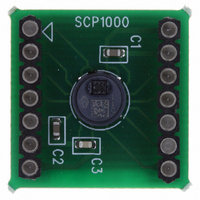
SCP1000 PCB3
Manufacturer Part Number
SCP1000 PCB3
Description
SENSOR I2C 30-120KPA PCB
Manufacturer
VTI Technologies
Series
SCP1000r
Datasheet
1.SCP1000_PCB3.pdf
(37 pages)
Specifications of SCP1000 PCB3
Pressure Type
Absolute
Operating Pressure
4.35 ~ 17.40 PSI, 30 ~ 120 kPa
Output
Digital
Voltage - Supply
2.4 V ~ 3.3 V
Termination Style
Surface Mount
Operating Temperature
-20°C ~ 70°C
Package / Case
PCB Mount
Lead Free Status / RoHS Status
Lead free / RoHS Compliant
Other names
551-1044


2.1.2.2
2.2 Measurement Modes
2.2.1
2.2.1.1
VTI Technologies Oy
www.vti.fi
Measurement modes timing and real time constraints
SCP1000 checksum error check (optional)
Continuous measurement modes
The DATARD8 register (address 0x1F when using SPI interface or 0x7F when using TWI interface)
can be read in order to check the EEPROM checksum error (see Figure 3). If the content of
DATARD8 is 0x00, EEPROM checksum calculation indicated an error and the start-up procedure is
failed. Correct EEPROM checksum calculation result is indicated by content of 0x01 in DATARD8.
SCP1000 pressure sensor measurement modes are presented in Table 2 below. In three of the
measurement modes SCP1000 samples pressure and temperature continuously. In low power
mode SCP1000 measures pressure and temperature once after the measurement is triggered.
Table 2. SCP1000 measurement modes.
In continuous measurement mode the output data is refreshed after each measurement and the
availability of the updated pressure and temperature data is signaled through the assertion of the
DRDY pin and a DRDY bit is set to ‘1’ in the STATUS register.
In Figure 4 is presented the timing diagram in the continuous measurement modes.
Figure 4. Timing diagram in continuous measurement mode.
In order to clear the DRDY signal, the host processor has to read the pressure output data. The
temperature output data is updated before the pressure output data, thus the time to service the
DRDY (T
In the case that the temperature data is not needed, the time for servicing the DRDY interrupt can
be extended. In any case, the DRDY interrupt must be serviced (the pressure data reading has to
be completed) before the next pressure data update.
DRDY pin
TRIG pin
SCP1000
Measurement
mode
High resolution
High speed
Ultra low power
Low power
Interface
Activity
Update
Output
Status
CLR
in Figure 4) is shorter than the measurement and computation time (T
Measurement and computation
TEMP
UPDATE
(No. N+1)
Activation code
0x0C or TRIG pin
T
MEAS
0x0A
0x0B
0x09
PRESSURE
(No. N+1)
UPDATE
Doc.Nr. 8260800.08
Subject to changes
17 bits or 15 bits
Resolution
T
Measurement and computation
17 bits
15 bits
15 bits
CLR
TEMP
UPDATE
(No. N+2)
Measurement
Continuous
Continuous
Continuous
Triggered
PRESSURE
type
(No. N+2)
UPDATE
MEAS
SCP1000 Series
in Figure 4).
Rev.0.08
9/37
Related parts for SCP1000 PCB3
Image
Part Number
Description
Manufacturer
Datasheet
Request
R


Part Number:
Description:
SENSOR 30-120KPA SPI
Manufacturer:
VTI Technologies
Datasheet:

Part Number:
Description:
SENSOR SPI 30-120KPA PCB
Manufacturer:
VTI Technologies
Datasheet:

Part Number:
Description:
SENSOR I2C 30-120KPA
Manufacturer:
VTI Technologies
Datasheet:

Part Number:
Description:
ACCELEROMETER SGL 1.7G DIL8 SMD
Manufacturer:
VTI Technologies
Datasheet:

Part Number:
Description:
VTI Automotive Digital Accelerometer Platform
Manufacturer:
VTI [VTI technologies]
Datasheet:

Part Number:
Description:
BOARD PWB ACCEL 3-AXIS SPI/I2C
Manufacturer:
VTI Technologies
Datasheet:

Part Number:
Description:
EVAL BOARD ACCELEROMETER Y-AXIS
Manufacturer:
VTI Technologies
Datasheet:

Part Number:
Description:
EVAL BOARD INCLINOMETER Y-AXIS
Manufacturer:
VTI Technologies
Datasheet:

Part Number:
Description:
KIT DEMO ACCELEROMTR CMA3000-D01
Manufacturer:
VTI Technologies
Datasheet:
Part Number:
Description:
ACCELEROMETER SGL 1.7G DIL8 SMD
Manufacturer:
VTI Technologies
Datasheet:
Part Number:
Description:
VTI Automotive Digital Accelerometer Platform
Manufacturer:
VTI [VTI technologies]
Datasheet:
Part Number:
Description:
Accelerometer
Manufacturer:
VTI [VTI technologies]
Datasheet:
Part Number:
Description:
Stand Alone Inclinometer
Manufacturer:
VTI [VTI technologies]
Datasheet:
Part Number:
Description:
3-axis accelerometer
Manufacturer:
VTI [VTI technologies]
Datasheet: