IS-CL01-F-E NKK Switches, IS-CL01-F-E Datasheet - Page 19
IS-CL01-F-E
Manufacturer Part Number
IS-CL01-F-E
Description
SMARTSWITCH CONTROLLER OLED
Manufacturer
NKK Switches
Datasheet
1.IS-DEV_KIT-7D.pdf
(24 pages)
Specifications of IS-CL01-F-E
Accessory Type
Controller
Description/function
SMARTSWITCH Development Kit
For Use With/related Products
OLED SmartSwitch™
For Use With
360-2344 - SWITCH OLED 64RGB X 48
Lead Free Status / RoHS Status
Contains lead / RoHS non-compliant
Other names
360-2424


7850 East Gelding Drive • Scottsdale, AZ 85260-3420
6. Hardware
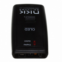
Controls Overview
The Mode Select Switch has two settings; “Switch” is for the OLED (64x48) switches and “Display” is for the
OLED (52x36) displays.
The Connector is for the installation of the Logic Boards onto the controller. One pin is keyed to reduce miss
mates.
The Batt/PWR switch has three positions: battery, off, line power.
Buzzer Volume adjusts the volume of the buzzer that activates when a button is pushed.
The 9V DC Power jack mates with a 2.5mm cylinder power connector. Center positive.
The RS232 Connector links the controller to the host.
Note: To turn off the controller, press both switches at the same time until the switches are off then
turn off the Batt/PWR switch. This step must be followed to comply with OLED power off
requirement.
CL01 Intelligent Controller Users Manual B.doc
Note: Improper installation of the Logic Boards could damage either/both the Logic Board and
Toll Free 1.877.2BUYNKK (877.228.9655) • Phone 480.991.0942 • Fax 480.998.1435
RS232
CL01 Intelligent Controller Users Manual
www.nkkswitches.com • Email engineering@nkkswitches.com
1
2
GND
controller.
3
TX
4
RX
5
GND
6
Page 19 of 24
0110
Related parts for IS-CL01-F-E
Image
Part Number
Description
Manufacturer
Datasheet
Request
R

Part Number:
Description:
PLUG, STANDARD, QUICKWIRE, T/C TYPE J
Manufacturer:
LABFACILITY
Datasheet:

Part Number:
Description:
SOCKET, STANDARD, T/C TYPE K
Manufacturer:
LABFACILITY
Datasheet:
Part Number:
Description:
PLUG, STANDARD, QUICKWIRE, T/C TYPE K
Manufacturer:
LABFACILITY
Datasheet:

Part Number:
Description:
SOCKET, STANDARD PANEL, T/C TYPE K
Manufacturer:
LABFACILITY
Datasheet:

Part Number:
Description:
SOCKET, STANDARD, T/C TYPE T
Manufacturer:
LABFACILITY
Datasheet:

Part Number:
Description:
PLUG, STANDARD, T/C TYPE T
Manufacturer:
LABFACILITY
Datasheet:

Part Number:
Description:
CONNECTOR, STNDRD, PAIR, T/C TYPE J
Manufacturer:
LABFACILITY
Datasheet:

Part Number:
Description:
CONNECTOR, STNDRD, PAIR, T/C TYPE K
Manufacturer:
LABFACILITY
Datasheet:

Part Number:
Description:
SMARTSWITCH DEMONSTRATION KIT 1
Manufacturer:
NKK Switches
Datasheet:

Part Number:
Description:
SMARTDISPLAY DEMONSTRATION KIT 2
Manufacturer:
NKK Switches
Datasheet:

Part Number:
Description:
LED Displays PROGRAMMABLE SWITCH
Manufacturer:
NKK Switches

Part Number:
Description:
ON-OFF PLATE - SERIES -EMP
Manufacturer:
NKK Switches
Datasheet:

Part Number:
Description:
WRENCH SOCKET FOR KB SERIES PB
Manufacturer:
NKK Switches
Datasheet:

Part Number:
Description:
SWITCH TOGGLE DPST 25A SLDR 5PCS
Manufacturer:
NKK Switches
Datasheet:

Part Number:
Description:
SWITCH TOGGLE DPDT 15A SLDR 5PC
Manufacturer:
NKK Switches
Datasheet: