IS-CL01-F-E NKK Switches, IS-CL01-F-E Datasheet - Page 4
IS-CL01-F-E
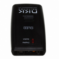
Manufacturer Part Number
IS-CL01-F-E
Description
SMARTSWITCH CONTROLLER OLED
Manufacturer
NKK Switches
Datasheet
1.IS-DEV_KIT-7D.pdf
(24 pages)
Specifications of IS-CL01-F-E
Accessory Type
Controller
Description/function
SMARTSWITCH Development Kit
For Use With/related Products
OLED SmartSwitch™
For Use With
360-2344 - SWITCH OLED 64RGB X 48
Lead Free Status / RoHS Status
Contains lead / RoHS non-compliant
Other names
360-2424


7850 East Gelding Drive • Scottsdale, AZ 85260-3420
3. Operational Overview
Power-up Sequence:
Upon power up, the controller checks the position of the Mode Select Switch and adjusts the image size
accordingly. The “Switch” position will show the full image while the “Display” position will display only the
middle 52 pixels of the top 36 lines of the image.
OLED Brightness Adjustment Mode:
The controller will then allow the brightness of the two OLED modules to be adjusted. Press the left hand
switch to make both OLED modules dimmer. Press the right hand switch to make both OLED modules brighter.
The brightness can be one of 16 levels between 0 and F where F is the maximum brightness. At the F level the
OLED has a rated life of 15,000 hours. The dimmer the level is set the longer the life of the OLED.
Main Operational Mode:
After a few seconds of user inactivity the controller will move into the main operations mode where the switch
on the left displays the image at the user’s first preset address. The right hand switch will display the image at
the user’s second preset address. The controller will then respond to a switch actuation or a timer expiration as
set by the attributes.
Addresses:
The controller associates one address to the left switch and one address to the right switch. Each switch will
display the image at their associated addresses. The addresses are in hexadecimal. The controller handles the
addresses as a group of addresses with associated images and attributes within user defined loops. Each loop has
a starter address and an ending address. The function of the attributes for each address is to tell the controller
where to point to next either when the switch associated with that particular address is pressed or when a timer
expires. There are three types of attributes:
• Attributes SW1 and SW2 are the Action Addresses. In the starting address the Action Addresses tell the
• The end address, EP1, sets the ending address for the loop.
• T1 and T2 are timers that are multiplied together to set the length of time to stay at one address before
The only addresses that need attributes within the loop are the first and last addresses.
Illustration 1 shows the starting and ending addresses for “Switch A” which is associated with address 0001H.
Switch A could be the left or right switch.
controller what addresses to point to when the switch associated with that particular address is pressed. In
the ending address the Action Addresses tell the controller what addresses to point to when the loop has
ended.
moving to the next address within the loop.
CL01 Intelligent Controller Users Manual B.doc
Toll Free 1.877.2BUYNKK (877.228.9655) • Phone 480.991.0942 • Fax 480.998.1435
CL01 Intelligent Controller Users Manual
www.nkkswitches.com • Email engineering@nkkswitches.com
Page 4 of 24
0110
Related parts for IS-CL01-F-E
Image
Part Number
Description
Manufacturer
Datasheet
Request
R

Part Number:
Description:
PLUG, STANDARD, QUICKWIRE, T/C TYPE J
Manufacturer:
LABFACILITY
Datasheet:

Part Number:
Description:
SOCKET, STANDARD, T/C TYPE K
Manufacturer:
LABFACILITY
Datasheet:
Part Number:
Description:
PLUG, STANDARD, QUICKWIRE, T/C TYPE K
Manufacturer:
LABFACILITY
Datasheet:

Part Number:
Description:
SOCKET, STANDARD PANEL, T/C TYPE K
Manufacturer:
LABFACILITY
Datasheet:

Part Number:
Description:
SOCKET, STANDARD, T/C TYPE T
Manufacturer:
LABFACILITY
Datasheet:

Part Number:
Description:
PLUG, STANDARD, T/C TYPE T
Manufacturer:
LABFACILITY
Datasheet:

Part Number:
Description:
CONNECTOR, STNDRD, PAIR, T/C TYPE J
Manufacturer:
LABFACILITY
Datasheet:

Part Number:
Description:
CONNECTOR, STNDRD, PAIR, T/C TYPE K
Manufacturer:
LABFACILITY
Datasheet:

Part Number:
Description:
SMARTSWITCH DEMONSTRATION KIT 1
Manufacturer:
NKK Switches
Datasheet:

Part Number:
Description:
SMARTDISPLAY DEMONSTRATION KIT 2
Manufacturer:
NKK Switches
Datasheet:

Part Number:
Description:
LED Displays PROGRAMMABLE SWITCH
Manufacturer:
NKK Switches

Part Number:
Description:
ON-OFF PLATE - SERIES -EMP
Manufacturer:
NKK Switches
Datasheet:

Part Number:
Description:
WRENCH SOCKET FOR KB SERIES PB
Manufacturer:
NKK Switches
Datasheet:

Part Number:
Description:
SWITCH TOGGLE DPST 25A SLDR 5PCS
Manufacturer:
NKK Switches
Datasheet:

Part Number:
Description:
SWITCH TOGGLE DPDT 15A SLDR 5PC
Manufacturer:
NKK Switches
Datasheet: