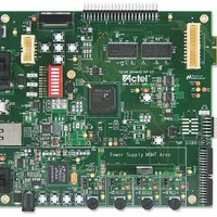
M1AFS-ADV-DEV-KIT-PWR Actel, M1AFS-ADV-DEV-KIT-PWR Datasheet - Page 32

M1AFS-ADV-DEV-KIT-PWR
Manufacturer Part Number
M1AFS-ADV-DEV-KIT-PWR
Description
MCU, MPU & DSP Development Tools Fusion Advanced Dev Kit w/ Power
Manufacturer
Actel
Datasheet
1.M1AFS-ADV-DEV-KIT-PWR.pdf
(94 pages)
Specifications of M1AFS-ADV-DEV-KIT-PWR
Processor To Be Evaluated
M1AFS1500-FGG484
Interface Type
Ethernet, USB, I2C, UART
Operating Supply Voltage
1.5 V to 5 V
Lead Free Status / RoHS Status
Lead free / RoHS Compliant
Hardware Components
Interface Connector
32
A standard interface connector on the board can be used to extend this development kit to connect with additional
daughter cards, some of which are developed by partners and third party vendors
possibilities are numerous, such as flash and SRAM memory interfaces, keyboard (HMI) interfaces, LCD interfaces,
and motor control interfaces.
CAUTION: I/Os on this connector are shared between this connector and the 44-pin legacy connector. Only one
daughter board can be connected at a time.
Note:
Note:
{5}
CAN_TXD_GPIO39_EXP
P8051_RXDAp_GPIO41_EXP
P8051_RXDAn_GPIO34_EXP
P8051_RXDBp_GPIO32_EXP
P8051_RXDBn_GPIO31_EXP
CH1_F2D_A_5V_GPIO33_EXP
CH1_F2D_B_5V_GPIO27_EXP
CH2_F2D_A_5V_GPIO22_EXP
CH2_F2D_B_5V_GPIO20_EXP
CH3_F2D_A_5V_GPIO12_EXP
CH3_F2D_B_5V_GPIO13_EXP
CH4_F2D_A_5V_GPIO17_EXP
CH4_F2D_B_5V_GPIO19_EXP
HI_LO_5V_GPIO24_EXP
F2D_TESTA_5V_GPIO21_EXP
GPIO38
CH4_D2F_B_5V_GPIO15_EXP
Mating Connector – Mating Connector Part Number: MEC1-120-02-F-S-EM2 (Manufacturer: Samtec)
Pin No:15 & 16 Should be NC For Mating Connector Polarized Pins
LAYOUT NOTE: R72, R73, R74, R75 SHOULD BE PLACED NEAR THE DUT
To design new interfaces on this connector, run a complete power analysis of your design to check for the available
power budget.
U
n
R
e
g
u
a l
e t
d
S
u
p
p
Figure 2-23 · Interface Connector Schematic
y l
R73
R73
V5V
39
39
20x2 Edge Fingers
11
13
17
19
21
23
25
27
29
31
33
35
37
39
1
3
5
7
9
HDR_20x2
HDR_20x2
J8
J8
Fusion Advanced Development Kit User’s Guide
2
4
6
8
10
12
14
18
20
22
24
26
28
30
32
34
36
38
40
R74
R74
R75
R75
R72
R72
V3P3
(Figure
39
39
39
39
39
39
R
e
g
GPIO10 {5}
GPIO40 {5}
GPIO43 {5}
P8051_TXDAn_GPIO42_EXP
P8051_TXDBp_GPIO35_EXP
P8051_TXDBn_GPIO30_EXP
P8051_TXINHIBITA_GPIO29_EXP
P8051_TXINHIBITB_GPIO28_EXP
P8051_RXSTROBEA_GPIO26_EXP
P8051_RXSTROBEB_GPIO25_EXP
CH1_D2F_A_5V_GPIO23_EXP
CH1_D2F_B_5V_GPIO37_EXP
CH2_D2F_A_5V_GPIO36_EXP
CH2_D2F_B_5V_GPIO11_EXP
CH3_D2F_A_5V_GPIO14_EXP
CH3_D2F_B_5V_GPIO18_EXP
CH4_D2F_A_5V_GPIO16_EXP
2-23). The interface
u
a l
e t
d
S
u
p
p
y l


