M1AFS-ADV-DEV-KIT-PWR Actel, M1AFS-ADV-DEV-KIT-PWR Datasheet - Page 56
M1AFS-ADV-DEV-KIT-PWR
Manufacturer Part Number
M1AFS-ADV-DEV-KIT-PWR
Description
MCU, MPU & DSP Development Tools Fusion Advanced Dev Kit w/ Power
Manufacturer
Actel
Datasheet
1.M1AFS-ADV-DEV-KIT-PWR.pdf
(94 pages)
Specifications of M1AFS-ADV-DEV-KIT-PWR
Processor To Be Evaluated
M1AFS1500-FGG484
Interface Type
Ethernet, USB, I2C, UART
Operating Supply Voltage
1.5 V to 5 V
Lead Free Status / RoHS Status
Lead free / RoHS Compliant


Manufacturing Test
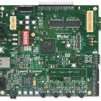
Hooking Up the Board and Ethernet Cable
56
2.
3.
4.
5.
6.
7.
Connect an Ethernet cable from the local area network to J9, the M1AFS-ADV-DEV-KIT Ethernet jack.
Connect one end of USB mini B cables to the USB connections on the M1AFS-ADV-DEV-KIT board and the
Actel programming stick. These connections are labeled USB 1 and USB 2 in
Connect the USB cables to the PC you will use for testing.
Connect one end of a 9 V power supply to power input, Power1, on the M1AFS-ADV-DEV-KIT board, as seen in
Figure C-1 on page
outlet.
When push-button SW15 is pressed after power-up, LED DM4 should light up.
Flip on power switch SW7 on the board. LEDs labeled D5 and D21 should light up. The LED labeled D3 on the
programming stick should also be lighted.
Flip on power switch SW17 on the board. LEDs labeled DM1, DM2, DM3, and DM4 should light up.
Note:
For the board Ethernet test to pass, the local network must be running a DHCP server that assigns an IP
address to the web server on the board. Network firewalls must not block the board web server.
55. Connect the end of another supply to input Power2. Plug both supplies into an electrical
Fusion Advanced Development Kit User’s Guide
Figure C-1 on page
55.
Related parts for M1AFS-ADV-DEV-KIT-PWR
Image
Part Number
Description
Manufacturer
Datasheet
Request
R

Part Number:
Description:
MCU, MPU & DSP Development Tools Fusion Advanced Development Kit
Manufacturer:
Actel
Part Number:
Description:
MCU, MPU & DSP Development Tools Silicon Sculptor Programming Mod
Manufacturer:
Actel
Part Number:
Description:
MCU, MPU & DSP Development Tools InSystem Programming ProASICPLUS Devices
Manufacturer:
Actel
Part Number:
Description:
Programming Socket Adapters & Emulators PQ160 Module
Manufacturer:
Actel
Part Number:
Description:
Programming Socket Adapters & Emulators Axcelerator Adap Module Kit
Manufacturer:
Actel
Part Number:
Description:
Programming Socket Adapters & Emulators Evaluation
Manufacturer:
Actel
Part Number:
Description:
Programming Socket Adapters & Emulators AFDX Solutions
Manufacturer:
Actel
Part Number:
Description:
Programming Socket Adapters & Emulators SILICON SCULPTOR ADAPTER MODULE
Manufacturer:
Actel
Datasheet:
Part Number:
Description:
Programming Socket Adapters & Emulators Axcelerator Adap Module Kit
Manufacturer:
Actel
Part Number:
Description:
Programming Socket Adapters & Emulators Evaluation
Manufacturer:
Actel
Part Number:
Description:
Programming Socket Adapters & Emulators Silicon Sculptor Software
Manufacturer:
Actel
Part Number:
Description:
Programming Socket Adapters & Emulators InSystem Programming ProASICPLUS Devices
Manufacturer:
Actel
Part Number:
Description:
Programming Socket Adapters & Emulators Evaluation
Manufacturer:
Actel
Part Number:
Description:
Programming Socket Adapters & Emulators Axcelerator Adap Module Kit
Manufacturer:
Actel
Part Number:
Description:
Programming Socket Adapters & Emulators Axcelerator Adap Module Kit
Manufacturer:
Actel