M1AFS-ADV-DEV-KIT-PWR Actel, M1AFS-ADV-DEV-KIT-PWR Datasheet - Page 39
M1AFS-ADV-DEV-KIT-PWR
Manufacturer Part Number
M1AFS-ADV-DEV-KIT-PWR
Description
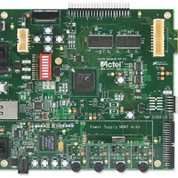
MCU, MPU & DSP Development Tools Fusion Advanced Dev Kit w/ Power
Manufacturer
Actel
Datasheet
1.M1AFS-ADV-DEV-KIT-PWR.pdf
(94 pages)
Specifications of M1AFS-ADV-DEV-KIT-PWR
Processor To Be Evaluated
M1AFS1500-FGG484
Interface Type
Ethernet, USB, I2C, UART
Operating Supply Voltage
1.5 V to 5 V
Lead Free Status / RoHS Status
Lead free / RoHS Compliant


Mixed-Signal Header
Fusion Advanced Development Kit User’s Guide
A range of Fusion mixed-signal pins, particularly the analog AV, AC, AG, and AT pins of the Analog Quad and GPIO
I/O pins, is available on the mixed-signal header on this board
daughter boards to access the Fusion analog pins to demonstrate various applications, such as motor control, touch
screen, and voltage trimming.
Note:
A thermistor circuit is available to use with the mixed-signal header for temperature monitor applications
To design new interfaces on this connector, run a complete power analysis of your design to check for the available
power budget.
R
e
g
{5}
{5}
{5}
{5}
{5}
{5}
{5}
{7}
{7}
{7}
{7}
{7}
{7}
{7}
{7}
{7}
u
a l
GPIO49
GPIO1
GPIO4
GPIO6
GPIO7
GPIO44
GPIO47
AG2
AG5
AV2
AV3
AV5
AV6
AT4
AG4
PWM1
e t
d
S
u
p
p
y l
Figure 2-33 · Mixed-Signal Header Schematic
V5V
Part Number :LTMM-120-02-T-D-RA
Manufacturer: SAMTEC
Mating Connector Part Number: SQT-120-01-L-D-RA
Manufacturer: Samtec
Figure 2-34 · Thermistor Schematic
11
13
15
17
19
21
23
25
27
29
31
33
35
37
39
R69
R69
R70
R70
10K
10K
1
3
5
7
9
V3P3A
0
0
J10
J10
MIXED_CONN40
MIXED_CONN40
R68
R68
0
0
AV2
AG2
AV3
AV5
AGND1
AV6
AT4
AG4
AG5
GPIO49
GPIO1
GND1
GPIO4
GPIO6
GPIO7
GPIO44
GND3
GPIO47
PWM1
VUSB
THERMTR
THERM1
GPIO50
GPIO45
GPIO46
GPIO48
AGND2
AGND3
GPIO2
GPIO3
GPIO5
GPIO8
PWM2
GND2
(Figure
V3P3
AG3
AG6
AC2
AC3
AC5
AC6
AT4 {7}
2
4
6
8
10
12
14
16
18
20
22
24
26
28
30
32
34
36
38
40
Components Descriptions and Connections
2-33.) This header can be used by various
LAYOUT NOTE: R71 AND R77
SHOULD BE PLACED NEAR THE DUT
R71
R71
R77
R77
V3P3
THERM1
R
39
39
39
39
e
g
u
a l
e t
d
S
GPIO50 {5}
GPIO2 {5}
GPIO3 {5}
GPIO5 {5}
GPIO8 {5}
GPIO45 {5}
GPIO46 {5}
GPIO48 {5}
PWM2 {7}
AC2 {7}
AC3 {7}
AC5 {7}
AG3 {7}
AC6 {7}
AG6 {7}
u
p
(Figure
p
y l
2-34).
39
Related parts for M1AFS-ADV-DEV-KIT-PWR
Image
Part Number
Description
Manufacturer
Datasheet
Request
R

Part Number:
Description:
MCU, MPU & DSP Development Tools Fusion Advanced Development Kit
Manufacturer:
Actel
Part Number:
Description:
MCU, MPU & DSP Development Tools Silicon Sculptor Programming Mod
Manufacturer:
Actel
Part Number:
Description:
MCU, MPU & DSP Development Tools InSystem Programming ProASICPLUS Devices
Manufacturer:
Actel
Part Number:
Description:
Programming Socket Adapters & Emulators PQ160 Module
Manufacturer:
Actel
Part Number:
Description:
Programming Socket Adapters & Emulators Axcelerator Adap Module Kit
Manufacturer:
Actel
Part Number:
Description:
Programming Socket Adapters & Emulators Evaluation
Manufacturer:
Actel
Part Number:
Description:
Programming Socket Adapters & Emulators AFDX Solutions
Manufacturer:
Actel
Part Number:
Description:
Programming Socket Adapters & Emulators SILICON SCULPTOR ADAPTER MODULE
Manufacturer:
Actel
Datasheet:
Part Number:
Description:
Programming Socket Adapters & Emulators Axcelerator Adap Module Kit
Manufacturer:
Actel
Part Number:
Description:
Programming Socket Adapters & Emulators Evaluation
Manufacturer:
Actel
Part Number:
Description:
Programming Socket Adapters & Emulators Silicon Sculptor Software
Manufacturer:
Actel
Part Number:
Description:
Programming Socket Adapters & Emulators InSystem Programming ProASICPLUS Devices
Manufacturer:
Actel
Part Number:
Description:
Programming Socket Adapters & Emulators Evaluation
Manufacturer:
Actel
Part Number:
Description:
Programming Socket Adapters & Emulators Axcelerator Adap Module Kit
Manufacturer:
Actel
Part Number:
Description:
Programming Socket Adapters & Emulators Axcelerator Adap Module Kit
Manufacturer:
Actel