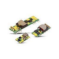
FPMR12TR7508NA Fujitsu, FPMR12TR7508NA Datasheet - Page 6

FPMR12TR7508NA
Manufacturer Part Number
FPMR12TR7508NA
Description
DC/DC Converters & Regulators 8A Neg SIP 6-14VIn .7525-5V Out
Manufacturer
Fujitsu
Datasheet
1.FPMR12TR7508PA.pdf
(26 pages)
Specifications of FPMR12TR7508NA
Output Power
40 W
Input Voltage Range
6 V to 14 V
Output Voltage (channel 1)
0.7525 V to 5 V
Output Current (channel 1)
8 A
Package / Case Size
SIP
Product
Non-Isolated / POL
Lead Free Status / RoHS Status
Lead free / RoHS Compliant
FPMR12TR7508*A
6-14Vdc Input, 8A, 0.7525-5.5Vdc Output
http://www.fdk.co.jp
Output Voltage Programming (Pin 2)
The
converter can be programmed from 0.7525V to 5.5V
by using an external resistor or a voltage source
FPMR12TR7508*Aの出力電圧は外部抵抗を接続するか、又は外部電
源を印加することで 0.7525V~5.5Vまで可変可能です。
External Resistor
An external trim resistor, R
between TRIM (pin 2) and GND (pin 3); see Fig. B.
The value of R
V
外部抵抗 R
ください。図Bを参照。 R
り求めます。
Note that the tolerance of a trim resistor will affect the
tolerance of the output voltage. Standard 1% or 0.5%
resistors may suffice for most applications; however, a
tighter tolerance can be obtained by using two
resistors in series insteed of one standard value
resistor.
Table 1 lists calculated values of R
output voltages. For each value of R
shows the closest available standard resistor value.
R
いては、標準的な1%又は0.5%品の抵抗で十分です。しかしながら、より厳
しい出力精度のためには、抵抗1本よりも2本を直列に使用します。
Table 1に一般的な出力電圧を設定する際の抵抗値を表示します。また
Table 1に標準的な抵抗を使用した場合の近似値も表示しています。
TRIM
Vin
O-REQ
Fig. B: Configuration for programming output voltage
R
の公差は出力電圧の公差に影響します。ほとんどの使用状況にお
TRIM
, in V, is given by:
output
TRIM
=
はTRIM端子(2番ピン)とGND端子(3番ピン)の間に接続して
(V
O
TRIM
voltage
-REQ
10.5
TRIM
, in kΩ, for a desired output voltage,
-
Vin
On/off
GND
0.7525)
の定数、及び必要な出力電圧は次の式によ
of
Delivering Next Generation Technology
TRIM
the
1 -
, should be connected
k [
Ω
FPMR12TR7508*A
TRIM
Vout
]
TRIM
TRIM
, Table 1 also
for common
R
Load
T RIM
Page 6 of 26
External Voltage Source
To program the output voltage using an external
voltage source, a voltage, V
the TRIM pin. Use of a series resistor, R
the TRIM pin and the programming voltage source is
recommended to make trimming less sensitive.
外部電源を使って出力電圧を可変するには、TRIM端子にV
印加します。電圧設定が敏感すぎるのを避けるため、TRIM端子と外部
電源間に抵抗を直列に接続することをお勧めします。
The voltage of the control voltage V
given volue of R
V
Table 2 lists values of V
R
Table 2はR
CTRL
EXT
V
電圧は下記の式により算出が可能です。
V
0.7525
O-REG
=15kΩ.
V
O-REG
0.7525
1.0
1.2
1.5
1.8
2.0
2.5
3.3
5.0
5.5
CTRL
1.0
1.2
1.5
1.8
2.0
2.5
3.3
5.0
5.5
EXT
[V]
[V]
=0の時とR
=
0.7
Table 2: Control Voltage [Vdc]
Table 1: Trim Resistor Value
EXT
-
(1
EXT
R
, in kΩ, is given by:
+
TRIM
V
=15kの時のV
Open
41.42
22.46
13.05
9.02
7.42
5.01
3.12
1.47
1.21
R
CTRL
EXT
[kΩ]
0.700
0.684
0.670
0.650
0.630
0.617
0.584
0.530
0.417
0.384
(R
)(V
EXT
CTRL
O
15
=0)
CTRL
-REQ
CTRL
Ver 2.3 Aug. 31, 2007
, should be applied to
電圧を表しています。
Standard Value [kΩ]
-
CTRL
0.7525)
for R
The Closest
V
CTRL
, in V, for a
Series
41.2
22.6
13.0
9.09
7.50
4.99
3.09
1.47
1.21
EXT
-0.097
-0.417
-0.631
-1.164
-2.017
-3.831
-4.364
0.700
0.436
0.223
EXT
(R
, between
CTRL
EXT
[V]
=0 and
の電圧を
=15k)


