3059Y-1-500LF Bourns Inc., 3059Y-1-500LF Datasheet - Page 11
3059Y-1-500LF
Manufacturer Part Number
3059Y-1-500LF
Description
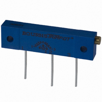
TRIMPOT 50 OHM 1.25"REC CER MT
Manufacturer
Bourns Inc.
Series
3059 - Sealedr
Specifications of 3059Y-1-500LF
Temperature Coefficient
±100ppm/°C
Resistance (ohms)
50
Termination Style
PC Pin
Power (watts)
1W
Tolerance
±10%
Number Of Turns
22
Adjustment Type
Side Adjustment
Resistive Material
Cermet
Mounting Type
Chassis Mount
Package / Case
Rectangular - 1.250" L x 0.190" W x 0.315" H (31.75mm x 4.83mm x 8.00mm)
Track Resistance
50ohm
No. Of Turns
22
Resistance Tolerance
± 10%
Power Rating
1W
Potentiometer Mounting
Through Hole
Resistance
50 Ohms
Operating Temperature Range
- 55 C to + 150 C
Element Type
Cermet
Dimensions
6.10 mm W x 31.75 mm L
Product
Trimmers
Taper
Linear
Rohs Compliant
Yes
Lead Free Status / RoHS Status
Lead free / RoHS Compliant
Lead Free Status / RoHS Status
Lead free / RoHS Compliant, Lead free / RoHS Compliant


float height gives the appropriate fuel volume signal to the fuel gauge. For this
reason, a custom fuel card is generally designed for each fuel tank model.
The first fuel senders were wirewound construction. However, in many instances
these units suffered from wire wear and breakages. The resistance profile of the
wirewound fuel sender also changed as the wire wore at different rates and
positions of the float arm. These problems were overcome with the introduction
of the thick-film fuel card. A variable resistor is achieved by tapping the resistor
traces with segmented conductor tracks creating a step-function output as shown
in Figure 6. If the wiper contact were to run directly on the cermet resistor, as in a
potentiometer, the required product life specification of at least 1 million wet
cycles would not be achieved. A tight resistance tolerance of each partial resistor
is achieved by laser trimming.
As the fuel card (resistor element) is immersed in fuel, its chemical resistance is of
great importance. The introduction of low-sulphur fuels for environmental
reasons has placed additional demands on conductor metallurgies.
Typical Fuel Card Designs
Termination
Figure 7: Fuel card design overview (Dual track design)
Figure 9: Single track design
Specifications are typical and dependent on
the manufacturing method, materials, size
and shape of the part.
pads
resistor
Feeder
Resistor traces
Ceramic Substrate
(Alumina)
Tape selector track
(Segmented conductor)
Collector track
(Solid conductor)
Figure 10: Linear track design
Trends
Figure 5: Typical fuel level indication circuit
Figure 6: Example of step-function output
Figure 8: Dual track design
sender
300
250
200
150
100
V
level
Fuel
50
in
cc
0
0
the fuel level sender market
Fuel Card Resistance Profile
10
Feeder resistor
20
Steps
30
Fuel gauge
40
50
60
9
Related parts for 3059Y-1-500LF
Image
Part Number
Description
Manufacturer
Datasheet
Request
R

Part Number:
Description:
POT 500K OHM 1-1/4" RECT CERM MT
Manufacturer:
Bourns Inc.
Datasheet:
Part Number:
Description:
POT 100 OHM 1-1/4" RECT CERM MT
Manufacturer:
Bourns Inc.
Datasheet:
Part Number:
Description:
POT 10K OHM 1-1/4" RECT CERM MT
Manufacturer:
Bourns Inc.
Datasheet:
Part Number:
Description:
POT 100K OHM 1-1/4" RECT CERM MT
Manufacturer:
Bourns Inc.
Datasheet:
Part Number:
Description:
POT 1.0K OHM 1-1/4" RECT CERM MT
Manufacturer:
Bourns Inc.
Datasheet:
Part Number:
Description:
POT 50K OHM 1-1/4" RECT CERM MT
Manufacturer:
Bourns Inc.
Datasheet:
Part Number:
Description:
POT 2.0K OHM 1-1/4" RECT CERM MT
Manufacturer:
Bourns Inc.
Datasheet:
Part Number:
Description:
POT 200K OHM 1-1/4" RECT CERM MT
Manufacturer:
Bourns Inc.
Datasheet:
Part Number:
Description:
POT 20K OHM 1-1/4" RECT CERM MT
Manufacturer:
Bourns Inc.
Datasheet:
Part Number:
Description:
POT 1.0M OHM 1-1/4" RECT CERM MT
Manufacturer:
Bourns Inc.
Datasheet:

Part Number:
Description:
Manufacturer:
Bourns, Inc.
Datasheet:
Part Number:
Description:
11mm Potentiometer
Manufacturer:
Bourns, Inc.
Datasheet: