3059Y-1-500LF Bourns Inc., 3059Y-1-500LF Datasheet - Page 152
3059Y-1-500LF
Manufacturer Part Number
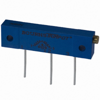
3059Y-1-500LF
Description
TRIMPOT 50 OHM 1.25"REC CER MT
Manufacturer
Bourns Inc.
Series
3059 - Sealedr
Specifications of 3059Y-1-500LF
Temperature Coefficient
±100ppm/°C
Resistance (ohms)
50
Termination Style
PC Pin
Power (watts)
1W
Tolerance
±10%
Number Of Turns
22
Adjustment Type
Side Adjustment
Resistive Material
Cermet
Mounting Type
Chassis Mount
Package / Case
Rectangular - 1.250" L x 0.190" W x 0.315" H (31.75mm x 4.83mm x 8.00mm)
Track Resistance
50ohm
No. Of Turns
22
Resistance Tolerance
± 10%
Power Rating
1W
Potentiometer Mounting
Through Hole
Resistance
50 Ohms
Operating Temperature Range
- 55 C to + 150 C
Element Type
Cermet
Dimensions
6.10 mm W x 31.75 mm L
Product
Trimmers
Taper
Linear
Rohs Compliant
Yes
Lead Free Status / RoHS Status
Lead free / RoHS Compliant
Lead Free Status / RoHS Status
Lead free / RoHS Compliant, Lead free / RoHS Compliant


Applications/Processing Guide – Standard and Lead Free
MECHANICAL TRAVEL — CLUTCHING ACTION: The total
MECHANICAL TRAVEL — CONTINUOUS ROTATION: The
ADJUSTMENT TRAVEL (ELECTRICAL): The total travel of
CONTINUITY TRAVEL: The total travel of the shaft over
Electrical and Operational Characteristics
TOTAL RESISTANCE: The DC resistance between the input
TEST VOLTAGE
NOTE: The test voltages should never exceed the equivalent of 10% rated power.
ABSOLUTE MINIMUM RESISTANCE: The resistance
END RESISTANCE: The resistance measured between the wiper
TEMPERATURE COEFFICIENT OF RESISTANCE: The unit
150
Total Resistance,
Nominal
(ohms)
.1 to 1.0
1.0 to 50
50 to 100
100 to 1000
1K to 100K
Over 0.1 megohm
the adjustment shaft between integral stops. Continuity must
be maintained throughout the travel.
travel of the adjustment shaft between the points where clutch
actuation begins. Continuity must be maintained throughout
the travel and during clutch actuation.
total travel of the adjustment shaft when the wiper movement
is unrestricted at either end of the resistive element as the
adjustment shaft continues to be actuated.
the adjustment shaft between minimum and maximum
output voltages.
which electrical continuity is maintained between the wiper
and the resistance element.
terminals with the wiper positioned to either end stop, or in
dead band for continuous rotation potentiometers.
measured between the wiper terminal and each end terminal
with the wiper positioned to give a minimum value.
terminal and an end terminal when the wiper is positioned at
the corresponding end of mechanical travel. Absolute
minimum resistance and end resistance are synonymous for
continuous rotation trimmers.
change in resistance per degree Celsius change from a
reference temperature, expressed in parts per million per
degree Celsius as follows:
The minimum voltage to be used is 10 MV.
Non-Wirewound
Maximum Test Voltage (Volts DC)
0.1
0.3
2.0
3.0
10
50
Wirewound
0.1
0.3
2.0
3.0
10
—
RESISTANCE-TEMPERATURE CHARACTERISTIC: The
CONTACT RESISTANCE VARIATION: The apparent
Where:
Figure 1. Contact-resistance-variation measuring circuit
NOTE: At the calibration of the decade, terminals 1 and 2 must be coincident.
Calibration decade is to be set for the contact-resistance variation (CRV) level of the
specified nominal resistance being tested.
CONSTANT
CURRENT
SOURCE
NOT TO EXCEED
RATING OF Rt
BEING TESTED
Where:
R
R
T
T
difference between the total resistance values measured at a
reference temperature of 25 °C and the specified test
temperature expressed as a percent of the Total Resistance.
Where:
R
R
resistance seen between the wiper and the resistance element
when the wiper is energized with a specified current and
moved over the adjustment travel in either direction at a
constant speed. The output variations are measured over a
specified frequency bandwidth, exclusive of the effects due to
roll-on or roll-off of the terminations and is expressed in
ohms or % of total resistance.
Rt = Test specimen
Output detector bandwidth = 100 cycles to 50 kilocycles
Minimum input impedance to output detector:
At least 10 times the nominal resistance being tested
1
2
1
2
1
2
CALIBRATION
DECADES
(SEE NOTE)
= Resistance at reference temperature in ohms.
= Resistance at test temperature in ohms.
= Reference temperature in degrees Celsius.
= Test temperature in degrees Celsius.
=
=
1
2
Rt
Resistance at reference temperature (25 °C) in ohms.
Resistance at the test temperature in ohms.
3
RTC = ——————— x 100
TC = ——————— x 10
OUTPUT DETECTOR
R
AC
AMPLIFIER
OR FILTER
1
R
R
(T
2
2
R
– R
– R
2
1
– T
1
1
1
)
6
OSCILLOSCOPE
Related parts for 3059Y-1-500LF
Image
Part Number
Description
Manufacturer
Datasheet
Request
R

Part Number:
Description:
POT 500K OHM 1-1/4" RECT CERM MT
Manufacturer:
Bourns Inc.
Datasheet:
Part Number:
Description:
POT 100 OHM 1-1/4" RECT CERM MT
Manufacturer:
Bourns Inc.
Datasheet:
Part Number:
Description:
POT 10K OHM 1-1/4" RECT CERM MT
Manufacturer:
Bourns Inc.
Datasheet:
Part Number:
Description:
POT 100K OHM 1-1/4" RECT CERM MT
Manufacturer:
Bourns Inc.
Datasheet:
Part Number:
Description:
POT 1.0K OHM 1-1/4" RECT CERM MT
Manufacturer:
Bourns Inc.
Datasheet:
Part Number:
Description:
POT 50K OHM 1-1/4" RECT CERM MT
Manufacturer:
Bourns Inc.
Datasheet:
Part Number:
Description:
POT 2.0K OHM 1-1/4" RECT CERM MT
Manufacturer:
Bourns Inc.
Datasheet:
Part Number:
Description:
POT 200K OHM 1-1/4" RECT CERM MT
Manufacturer:
Bourns Inc.
Datasheet:
Part Number:
Description:
POT 20K OHM 1-1/4" RECT CERM MT
Manufacturer:
Bourns Inc.
Datasheet:
Part Number:
Description:
POT 1.0M OHM 1-1/4" RECT CERM MT
Manufacturer:
Bourns Inc.
Datasheet:

Part Number:
Description:
Manufacturer:
Bourns, Inc.
Datasheet:
Part Number:
Description:
11mm Potentiometer
Manufacturer:
Bourns, Inc.
Datasheet: