3059Y-1-500LF Bourns Inc., 3059Y-1-500LF Datasheet - Page 158
3059Y-1-500LF
Manufacturer Part Number
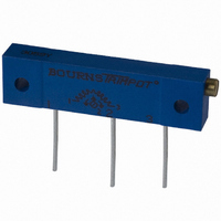
3059Y-1-500LF
Description
TRIMPOT 50 OHM 1.25"REC CER MT
Manufacturer
Bourns Inc.
Series
3059 - Sealedr
Specifications of 3059Y-1-500LF
Temperature Coefficient
±100ppm/°C
Resistance (ohms)
50
Termination Style
PC Pin
Power (watts)
1W
Tolerance
±10%
Number Of Turns
22
Adjustment Type
Side Adjustment
Resistive Material
Cermet
Mounting Type
Chassis Mount
Package / Case
Rectangular - 1.250" L x 0.190" W x 0.315" H (31.75mm x 4.83mm x 8.00mm)
Track Resistance
50ohm
No. Of Turns
22
Resistance Tolerance
± 10%
Power Rating
1W
Potentiometer Mounting
Through Hole
Resistance
50 Ohms
Operating Temperature Range
- 55 C to + 150 C
Element Type
Cermet
Dimensions
6.10 mm W x 31.75 mm L
Product
Trimmers
Taper
Linear
Rohs Compliant
Yes
Lead Free Status / RoHS Status
Lead free / RoHS Compliant
Lead Free Status / RoHS Status
Lead free / RoHS Compliant, Lead free / RoHS Compliant


Standard Soldering and Cleaning Processes
This application note is designed to
provide step-by-step processing
recommendations. It covers the popular
Surface Mount Component (SMC)
soldering processes currently in use and
provides recommendations and cautions
for each step. Since many variations of
temperature, time, processes, cleaning
agents and board types are found in the
156
1
Solder Paste
Printing
Reflow
GENERAL
Use the optimum
solder paste for the
pattern, printing
process, solder paste
density and solder
joint quality.
RECOMMENDED
Use Sn 63 % Pb 37 %
solder paste. Use 8 to
10 mil thickness for
solder paste print.
CAUTION
Since solder paste
usually contains a high
percentage of activators,
you must ensure
adequate cleaning to
remove all residues,
unless no-clean (low
solids) paste is used.
Adhesive
Application
2
Flow (Wave)
GENERAL
The adhesive must hold
the SMC in correct
orientation upon place-
ment and maintain
correct trimmer position
during physical
handling before final
solder processing.
RECOMMENDED
To assure positional
stability, place a single
dot of epoxy under the
SMC.
CAUTION
Stability after placement
is a direct function of
the volume of adhesive
used. Use enough epoxy
to assure stability
through the cure
process.
Avoid overflow of epoxy
to solder pad and
terminal areas.
EPOXY
electronics industry, you’ll want to test and
verify your own system.
The process steps, recommendations and
cautions are based on Bourns® Trimpot®
surveys of SMC users, equipment
manufacturers and materials suppliers.
Also, comments reflect results of Bourns
testing. Our findings suggest the following
soldering and cleaning processes:
SMC
Placement
3
GENERAL
Use pick-and-place
equipment with
vacuum nozzle ID size
that allows adequate
suction to pick the
SMC out of the
embossed cavity.
RECOMMENDED
The nozzle inside
diameter (ID) should
not exceed .100 in.
(2.54 mm) to ensure
adequate suction and
part alignment.
CAUTION
Assure parts are
placed so that all
terminals are
equidistant (<4 mils)
from the solder pads.
Align terminals with
solder belt direction of
travel to avoid body
shadowing effects
during flow soldering.
Adhesive
Cure
Flow (Wave)
GENERAL
Use heat/time cure
method with either
convection oven or
infrared radiation.
RECOMMENDED
Cure using the
temperature and
times recommended
by the adhesive
manufacturer.
CAUTION
Use enough cure
time to assure
complete adhesive
transition from fluid
to solid.
4
1. SOLDERING – Forced Hot Air,
2. CLEANING – Solvent, Aqueous, Semi-
On the facing page are the common
methods, materials and maximum
temperature/time parameters for soldering
and cleaning processes.
Convection, IR, Vapor Phase (In-Line),
Wave (Single and Dual)
Aqueous, No-Clean
Flux
Application
5
Flow (Wave)
GENERAL
Use the correct flux
to remove surface
oxides, prevent
reoxidation and
promote wetting.
RECOMMENDED
• RMA
• No-clean SRB
• OA (Organic Acid)
CAUTION
Avoid highly
activated fluxes.
Consult factory before
using OA.
(Synthetic Resin
Based)
(See caution)
Related parts for 3059Y-1-500LF
Image
Part Number
Description
Manufacturer
Datasheet
Request
R

Part Number:
Description:
POT 500K OHM 1-1/4" RECT CERM MT
Manufacturer:
Bourns Inc.
Datasheet:
Part Number:
Description:
POT 100 OHM 1-1/4" RECT CERM MT
Manufacturer:
Bourns Inc.
Datasheet:
Part Number:
Description:
POT 10K OHM 1-1/4" RECT CERM MT
Manufacturer:
Bourns Inc.
Datasheet:
Part Number:
Description:
POT 100K OHM 1-1/4" RECT CERM MT
Manufacturer:
Bourns Inc.
Datasheet:
Part Number:
Description:
POT 1.0K OHM 1-1/4" RECT CERM MT
Manufacturer:
Bourns Inc.
Datasheet:
Part Number:
Description:
POT 50K OHM 1-1/4" RECT CERM MT
Manufacturer:
Bourns Inc.
Datasheet:
Part Number:
Description:
POT 2.0K OHM 1-1/4" RECT CERM MT
Manufacturer:
Bourns Inc.
Datasheet:
Part Number:
Description:
POT 200K OHM 1-1/4" RECT CERM MT
Manufacturer:
Bourns Inc.
Datasheet:
Part Number:
Description:
POT 20K OHM 1-1/4" RECT CERM MT
Manufacturer:
Bourns Inc.
Datasheet:
Part Number:
Description:
POT 1.0M OHM 1-1/4" RECT CERM MT
Manufacturer:
Bourns Inc.
Datasheet:

Part Number:
Description:
Manufacturer:
Bourns, Inc.
Datasheet:
Part Number:
Description:
11mm Potentiometer
Manufacturer:
Bourns, Inc.
Datasheet: