EVL90WADP-LLCSR STMicroelectronics, EVL90WADP-LLCSR Datasheet - Page 25
EVL90WADP-LLCSR
Manufacturer Part Number
EVL90WADP-LLCSR
Description
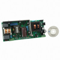
EVAL BOARD PORTABLE PWR SUPPLY
Manufacturer
STMicroelectronics
Type
Power Factor Correctionr
Datasheets
1.L6563HTR.pdf
(49 pages)
2.L6599ADTR.pdf
(36 pages)
3.EVL90WADP-LLCSR.pdf
(29 pages)
4.EVL90WADP-LLCSR.pdf
(28 pages)
Specifications of EVL90WADP-LLCSR
Main Purpose
AC/DC, Primary and Secondary Side with PFC
Outputs And Type
1, Isolated
Power - Output
90W
Voltage - Output
19V
Current - Output
4.75A
Voltage - Input
90 ~ 264VAC
Regulator Topology
Boost
Frequency - Switching
130kHz
Board Type
Fully Populated
Utilized Ic / Part
L6563H, L6599A, SRK2000
Input Voltage
90 V to 264 V
Output Voltage
19 V
Dimensions
65 mm x 155 mm
Product
Power Management Modules
Supply Current
4.75 A
Lead Free Status / RoHS Status
Lead free / RoHS Compliant
For Use With/related Products
L6563H, L6599A, SRK2000
Other names
497-10377


L6599A
Figure 28. Current sensing techniques: a) with sense resistor, b) “lossless”,
The L6599A is equipped with a current sensing input (pin 6, ISEN) and a sophisticated
overcurrent management system. The ISEN pin is internally connected to the input of a first
comparator, referenced to 0.8 V, and to that of a second comparator referenced to 1.5 V. If
the voltage externally applied to the pin by either circuit in
comparator is tripped and this causes an internal switch to be turned on and discharge the
soft-start capacitor C
frequency and thereby limit energy transfer. The discharge will go on until the voltage on the
ISEN pin has dropped by 50 mV; this, with an averaging time in the range of 10/f
an effective frequency rise. Under output short circuit, this operation results in a nearly
constant peak primary current.
It is normal that the voltage on the ISEN pin may overshoot above 0.8 V; however, if the
voltage on the ISEN pin reaches 1.5 V, the second comparator will be triggered, the L6599A
will shutdown and latch off with both the gate-drive outputs and the PFC_STOP pin low,
hence turning off the entire unit. The supply voltage of the IC must be pulled below the
UVLO threshold and then again above the start-up level in order to restart. Such an event
may occur if the soft-start capacitor C
or in case of transformer’s magnetizing inductance saturation or a shorted secondary
rectifier.
In the circuit shown in
low-side MOSFET is used, note the particular connection of the resonant capacitor. In this
way the voltage across Rs is related to the current flowing through the high-side MOSFET
and is positive most of the switching period, except for the time needed for the resonant
current to reverse after the low-side MOSFET has been switched off. Assuming that the time
constant of the RC filter is at least ten times the minimum switching frequency f
approximate value of Rs can be found using the empirical equation:
Equation 6
where I
and the primary winding of the transformer, which is related to the maximum load and the
minimum input voltage.
Crpkx
with capacitive shunt
is the maximum desired peak current flowing through the resonant capacitor
SS
Figure 28
(see
Section 7.3: Soft-start
Doc ID 15308 Rev 5
Rs
a, where a sense resistor Rs in series to the source of the
=
SS
Vs
I
Crpkx
pkx
is too large, so that its discharge is not fast enough
≈
5
I
Crpkx
⋅
0
8 .
). This will quickly increase the oscillator
≈
I
Crpkx
4
Figure 28
Application information
exceeds 0.8 V the first
min
min
, ensures
, the
25/36
Related parts for EVL90WADP-LLCSR
Image
Part Number
Description
Manufacturer
Datasheet
Request
R

Part Number:
Description:
STMicroelectronics [RIPPLE-CARRY BINARY COUNTER/DIVIDERS]
Manufacturer:
STMicroelectronics
Datasheet:
Part Number:
Description:
STMicroelectronics [LIQUID-CRYSTAL DISPLAY DRIVERS]
Manufacturer:
STMicroelectronics
Datasheet:

Part Number:
Description:
BOARD EVAL FOR MEMS SENSORS
Manufacturer:
STMicroelectronics
Datasheet:
Part Number:
Description:
NPN TRANSISTOR POWER MODULE
Manufacturer:
STMicroelectronics
Datasheet:
Part Number:
Description:
TURBOSWITCH ULTRA-FAST HIGH VOLTAGE DIODE
Manufacturer:
STMicroelectronics
Datasheet:
Part Number:
Description:
Manufacturer:
STMicroelectronics
Datasheet:
Part Number:
Description:
DIODE / SCR MODULE
Manufacturer:
STMicroelectronics
Datasheet:
Part Number:
Description:
DIODE / SCR MODULE
Manufacturer:
STMicroelectronics
Datasheet:
Part Number:
Description:
Search -----> STE16N100
Manufacturer:
STMicroelectronics
Datasheet:
Part Number:
Description:
Search ---> STE53NA50
Manufacturer:
STMicroelectronics
Datasheet:
Part Number:
Description:
NPN Transistor Power Module
Manufacturer:
STMicroelectronics
Datasheet:
Part Number:
Description:
DIODE / SCR MODULE
Manufacturer:
STMicroelectronics
Datasheet: