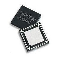
AX5043-QFN28-TU AXSEM, AX5043-QFN28-TU Datasheet - Page 24

AX5043-QFN28-TU
Manufacturer Part Number
AX5043-QFN28-TU
Description
RF Transceiver Narrow-Band-IC
Manufacturer
AXSEM
Datasheet
1.AX5043-QFN28-TU.pdf
(60 pages)
Specifications of AX5043-QFN28-TU
Number Of Receivers
1
Number Of Transmitters
1
Wireless Frequency
70 MHz to 1050 MHz
Interface Type
SPI
Output Power
18 dBm to 22 dBm
Operating Supply Voltage
1.8 V to 3.6 V
Maximum Operating Temperature
+ 85 C
Maximum Supply Current
60 mA
Minimum Operating Temperature
- 40 C
Modulation
ASK, FSK
Lead Free Status / RoHS Status
Lead free / RoHS Compliant
24
Circuit Description
5.2.
The
regulation with a tolerance of 0.5 ppm to 1.5 ppm depending on the regulation. The on-chip crystal
oscillator allows the use of an inexpensive quartz crystal as the RF generation subsystem’s timing
reference when regulatory and technical possible. The crystal oscillator circuit can handle a wide
range of crystal frequencies, it is recommended to use 16 MHz as reference frequency since this
choice allows all the typical SRD band RF frequencies to be generated with the internal VCO.
Programming the PWRMODE register enables the oscillator circuit. At power-up it is enabled.
To adjust the circuit’s characteristics to the quartz crystal being used, without using additional
external components, the tuning capacitance of the crystal oscillator can be programmed. The
transconductance of the oscillator is automatically regulated, to allow for fastest start-up times
together with lowest power operation during steady-state oscillation.
The integrated programmable tuning capacitor bank makes it possible to connect the oscillator
directly to pins CLK16N and CLK16P without the need for external capacitors. It is programmed
using bits XTALCAP[5:0] in register
To synchronize the receiver frequency to a carrier signal, the oscillator frequency could be tuned
using the capacitor bank however, the recommended method to implement frequency
synchronization is to make use of the high resolution RF frequency generation sub-system together
with the Automatic Frequency Control, both are described further down.
Alternatively a single ended reference (TXCO, CXO) may be used. The CMOS levels should be
applied to CLK16P via an AC coupling with the crystal oscillator enabled.
5.3.
The
frequency of oscillation is 640 Hz +/- 3%, in fast mode it is 10.2 kHz +/- 3%.
The low power oscillator makes a WOR mode with a power consumption of 400nA possible.
If Wake on Radio Mode is enabled, the receiver wakes up periodically at a user selectable interval,
and checks for a radio signal on the selected channel. If no signal is detected, the receiver shuts
down again. If a radio signal is detected, and a valid packet is received, the micro-controller is
alerted by asserting an interrupt.
The
powered down, and only wakes up once a valid packet is received. This allows for very low average
receiver power, at the expense of longer preambles at the transmitter.
5.4.
Pins DATA, DCLK, SYSCLK, IRQ, PWRAMP, ANTSEL can be used as general purpose I/O pins by
programming pin configuration registers
PINFUNCIRQ
PINSTATE
Version 0.2
AX5043
AX5043
AX5043
Crystal Oscillator
Low Power Oscillator and Wake on Radio (WOR) Mode
GPIO Pins
. Pull-ups are disabled if output data is programmed to the GPIO pin
is normally operated with an external TCXO, which is required by most narrow-band
,
features an internal lowest power fully integrated oscillator. In default-mode, the
can thus autonomously poll for radio signals, while the micro-controller can stay
PINFUCNANTSEL
,
XTALCAP
PINFUNCPWRAMP
Preliminary
PINFUNCSYSCLK
.
. Pin input values can be read via register
,
PINFUNCDCLK
,
Datasheet AX5043
PINFUNCDATA
,


