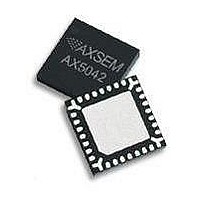
AX5043-QFN28-TU AXSEM, AX5043-QFN28-TU Datasheet - Page 26

AX5043-QFN28-TU
Manufacturer Part Number
AX5043-QFN28-TU
Description
RF Transceiver Narrow-Band-IC
Manufacturer
AXSEM
Datasheet
1.AX5043-QFN28-TU.pdf
(60 pages)
Specifications of AX5043-QFN28-TU
Number Of Receivers
1
Number Of Transmitters
1
Wireless Frequency
70 MHz to 1050 MHz
Interface Type
SPI
Output Power
18 dBm to 22 dBm
Operating Supply Voltage
1.8 V to 3.6 V
Maximum Operating Temperature
+ 85 C
Maximum Supply Current
60 mA
Minimum Operating Temperature
- 40 C
Modulation
ASK, FSK
Lead Free Status / RoHS Status
Lead free / RoHS Compliant
26
Circuit Description
The frequency must be programmed to the desired carrier frequency.
The synthesizer loop-bandwidth can be programmed.
VCO
An on-chip VCO converts the control voltage generated by the charge pump and loop filter into an
output frequency. This frequency is used for transmit as well as for receive operation. The
FREQ
frequency can be programmed in 1 Hz steps in the
registers. For operation in the 433 MHz
PLLVCODIV
band, the REFDIV bit in the
register must be programmed.
The fully integrated VCO allows operating the device in the frequency ranges 800 – 1040 MHz and
400 – 520 MHz.
The carrier frequency range can be extended to 140 – 800 MHz and 70 – 400 MHz by using an
PLLVCODIV
appropriate external inductor between device pins L1 and L2. The bit VCO2INT in the
register must be set high to enter this mode. See the Synthesizer Application Note for details on
how to set-up the synthesizer characteristics in this mode.
It is also possible to use a fully external VCO by setting bits VCO2INT=0 and VCOSEL=1 in the
PLLVCODIV
register. A differential input at a frequency of double the desired RF frequency must
be input at device pins L1 and L2. The control voltage for the VCO can be output at device pin FILT
when using external filter mode. The voltage range of this output pin is 0 – 1.8 V.
This mode of operation is recommended for special applications where the phase noise
requirements are not met when using the fully internal VCO or the internal VCO with external
inductor.
VCO Auto-Ranging
The
AX5043
has an integrated auto-ranging function, which allows to set the correct VCO range
for specific frequency generation subsystem settings automatically. Typically it has to be executed
PLLRANGINGA
after power-up. The function is initiated by setting the RNG_START bit in the
or
PLLRANGINGB
register. The bit is readable and a 0 indicates the end of the ranging process.
PLLRANGINGA
FREQA
Setting RNG_START in the
register ranges the frequency in
, while setting
PLLRANGINGB
FREQB
RNG_START in the
register ranges the frequency in
. The RNGERR bit
indicates the correct execution of the auto-ranging.
VCO auto-ranging works with the fully integrated VCO and with the internal VCO with external
inductor.
Loop Filter and Charge Pump
The
AX5043
internal loop filter configuration together with the charge pump current sets the
synthesizer loop bandwidth. The internal loop-filter has three configurations that can be
PLLLOOP
programmed via the register bits FLT[1:0] in register
the charge pump current can be
programmed using register bits PLLCPI[7:0]. Synthesizer bandwidths are typically 50 - 500 kHz..
Setting bits FLT[1:0]=00 bypasses the internal loop filter and the VCO control voltage is output to
an external loop filter at pin FILT. This mode of operation is recommended for achieving lower
bandwidths than with the internal loop filter and for usage with a fully external VCO.
Version 0.2
Preliminary
Datasheet AX5043


