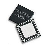
AX5043-QFN28-TU AXSEM, AX5043-QFN28-TU Datasheet - Page 27

AX5043-QFN28-TU
Manufacturer Part Number
AX5043-QFN28-TU
Description
RF Transceiver Narrow-Band-IC
Manufacturer
AXSEM
Datasheet
1.AX5043-QFN28-TU.pdf
(60 pages)
Specifications of AX5043-QFN28-TU
Number Of Receivers
1
Number Of Transmitters
1
Wireless Frequency
70 MHz to 1050 MHz
Interface Type
SPI
Output Power
18 dBm to 22 dBm
Operating Supply Voltage
1.8 V to 3.6 V
Maximum Operating Temperature
+ 85 C
Maximum Supply Current
60 mA
Minimum Operating Temperature
- 40 C
Modulation
ASK, FSK
Lead Free Status / RoHS Status
Lead free / RoHS Compliant
5.8.
The
Pin PWRAMP can be used to control an external RX/TX switch when operating the device together
with an external PA. Pin ANTSEL can be used to control an external antenna switch when receiving
with two antennas.
When antenna diversity is enabled, the radio controller will, when not in the middle of receiving a
packet, periodically probe both antennas and select the antenna with the highest signal strength.
The radio controller can be instructed to periodically write both RSSI values into the FIFO. Antenna
diversity mode is fully automatic.
LNA
The LNA amplifies the differential RF signal from the antenna and buffers it to drive the I/Q mixer.
An external matching network is used to adapt the antenna impedance to the IC impedance. A DC
feed to GND must be provided at the antenna pins.
I/Q Mixer
The RF signal from the LNA is mixed down to a low IF which depends on the selected data rate.
PA
In TX mode the PA drives the signal generated by the frequency generation subsystem out to
either the differential antenna terminals or to the single ended antenna pin. The antenna terminals
are chosen via the bits TXDIFF and TXSE in register
The output power of the PA is programmed via the register
The output amplitude can be shaped (raised cosine), this mode is selected with bit AMPLSHAPE in
register
1 – 8 bit times via bits SLOWRAMP in register
Output power as well as harmonic content will depend on the external impedance seen by the PA.
5.9.
The IF-channel-filter and the demodulator extract the data bit-stream from the incoming IF signal.
They must be programmed to match the modulation scheme as well as the data-rate. Inaccurate
programming will lead to loss of sensitivity.
Version 0.2
1. Both RX and TX use differential pins ANTP and ANTN. RX/TX switching is handled internally.
2. RX uses the differential antenna pins ANTP and ANTN. TX uses the single ended antenna
AX5043
RF Input and Output Stage (ANTP/ANTN/ANTP1)
IF-Channel-Filter and Demodulator
This mode is recommended for highest output powers, highest sensitivities and for direct
connection to dipole antennas.
pin ANTP1. RX/TX switching is handled externally. This can be done either with an external
RX/TX switch or with a direct tie configuration. This mode is recommended for low output
powers at high efficiency and for usage with external power amplifiers.
MODECFGA.
has two main antenna interface modes:
PA ramping is programmable in increments of the bit time and can be set to
Preliminary
MODECFGA.
MODECFGA
TXPWRCOEFFB
.
.
Circuit Description
Datasheet AX5043
27


