140-0000-973 Emerson Network Power, 140-0000-973 Datasheet - Page 10
140-0000-973
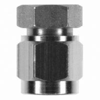
Manufacturer Part Number
140-0000-973
Description
CONN JACK SMA END LAUNCH FIXTURE
Manufacturer
Emerson Network Power
Series
SMAr
Specifications of 140-0000-973
Accessory Type
End Launch Connector
Product
Crimping, Stripping & Cutting Tools & Drills
Description/function
Soldering Mating Fixture for SMA Jacks
For Use With/related Products
SMA Jacks
Lead Free Status / RoHS Status
Not applicable / Not applicable
Lead Free Status / RoHS Status
Not applicable / Not applicable, Lead free / RoHS Compliant
Other names
J10081


High Frequency SMA End Launch Connectors
White Paper
Easily connected to GPCW transmission lines with
reproducible results
A coplanar waveguide transmission line is formed by a planar conductor separated by a pair of ground
planes, all on the same plane, atop of a high frequency dielectric medium. A variant is formed when a
ground plane is provided on the opposite side of the dielectric which is called grounded coplanar
waveguide (GCPW). Although GCPW is the preferred transmission line structure on the circuit board for
this connector, other lines such as microstrip can be used with good results.
At microwave frequencies, the coplanar waveguide can be equal to or better than the microstrip when
loss and dispersion are used as a basis for comparison. Minimum loss for a given coplanar waveguide
occurs at about 60 Ohms whereas the minimum loss for microstrip occurs at about 25 Ohms. A full wave
analysis which includes space wave and surface wave radiation shows that coplanar waveguide
discontinuities radiate much less energy than microstrip discontinuities.
The GCPW transmission line is fabricated on a high frequency circuit board substrate. Dielectric constant
control, low dissipation factor and controlled thicknesses differentiate these high frequency circuit board
materials from those typically used in the high volume printed circuit board world like FR4 and BT/epoxy.
For higher frequencies, dielectric loss becomes an important contributor to the total loss. This is
important because, as the frequency increases, the thickness of the material must decrease in order to
avoid generating transverse modes on the transmission lines.
The high frequency material’s low loss performance extends the useful range of these materials well
above 20 GHz. However, very thin dielectric layers as small as .008” are not mechanically stable enough
to support the connector and associated circuitry. Therefore, hybrid circuit board constructions
consisting of high frequency laminates and epoxy/glass substrates have become an increasingly utilized
alternative to lower overall circuit board costs. The DC, control and digital signal paths are designed onto
the lower cost epoxy/glass FR4 layer and the microwave signals are carried on the high frequency top
layer as shown in Figures 1A and 1B.
Figure 1A
Figure 1B
Typical HF/Digital Multilayer Hybrid Construction (GCPW Figure 1A, microstrip Figure 1B)
10
Emerson Network Power • Tel: 800.247.8256 • Fax 507.833.6287 • www.EmersonNetworkPower.com/connectivity
Related parts for 140-0000-973
Image
Part Number
Description
Manufacturer
Datasheet
Request
R

Part Number:
Description:
TRANSDUCERS SPECTROL / 140-0-0 50 OHM 1 SECT
Manufacturer:
Vishay

Part Number:
Description:
POT 2.0K OHM WW SINGLE TURN
Manufacturer:
Vishay
Datasheet:

Part Number:
Description:
POT 10K OHM WW SINGLE TURN
Manufacturer:
Vishay
Datasheet:

Part Number:
Description:
POT 1.0K OHM WW SINGLE TURN
Manufacturer:
Vishay
Datasheet:

Part Number:
Description:
POT 5.0K OHM WW SINGLE TURN
Manufacturer:
Vishay
Datasheet:

Part Number:
Description:
AC/DC Front end 12Vo 36A 12Vsb Standard Airflow
Manufacturer:
Emerson Network Power

Part Number:
Description:
POWER SUPPLY DIN 24VDC 10A
Manufacturer:
Emerson Network Power
Datasheet:

Part Number:
Description:
POWER SUPPLY SGL 48VOUT 40W 3X5"
Manufacturer:
Emerson Network Power
Datasheet:

Part Number:
Description:
POWER SUP MED&ITE 48V 45W 2"X4"
Manufacturer:
Emerson Network Power
Datasheet:

Part Number:
Description:
POWER SUPPLY 60W 12V OUT
Manufacturer:
Emerson Network Power
Datasheet:

Part Number:
Description:
POWER SUPPLY 60W 48V OUT
Manufacturer:
Emerson Network Power
Datasheet:

Part Number:
Description:
POWER SUPPLY 60W 15V OUT
Manufacturer:
Emerson Network Power
Datasheet:

Part Number:
Description:
POWER SUPPLY TRPL 3.3/5/12V 40W
Manufacturer:
Emerson Network Power
Datasheet:

Part Number:
Description:
POWER SUPPLY SWITCHER 24V 40W
Manufacturer:
Emerson Network Power
Datasheet:

Part Number:
Description:
Linear & Switching Power Supplies 24V output 25W 2A Medical &Non-Medical
Manufacturer:
Emerson Network Power
Datasheet: