140-0000-973 Emerson Network Power, 140-0000-973 Datasheet - Page 9
140-0000-973
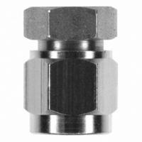
Manufacturer Part Number
140-0000-973
Description
CONN JACK SMA END LAUNCH FIXTURE
Manufacturer
Emerson Network Power
Series
SMAr
Specifications of 140-0000-973
Accessory Type
End Launch Connector
Product
Crimping, Stripping & Cutting Tools & Drills
Description/function
Soldering Mating Fixture for SMA Jacks
For Use With/related Products
SMA Jacks
Lead Free Status / RoHS Status
Not applicable / Not applicable
Lead Free Status / RoHS Status
Not applicable / Not applicable, Lead free / RoHS Compliant
Other names
J10081


Emerson Network Power • Tel: 800.247.8256 • Fax 507.833.6287 • www.EmersonNetworkPower.com/connectivity
Low VSWR and Insertion Loss over a Wide Bandwidth
An accurate characterization of packaged microwave circuits, such as broadband MMIC power
amplifiers, requires coaxial to planar transitions with low return and insertion loss. In order to achieve
low loss, the transition design between the launch connector and the printed circuit board requires the
optimization of both mechanical and electrical features. The mechanical design must physically match
the electromagnetic field distribution as close as possible in order to keep the discontinuity reactances
small, as shown in Figure 1. The electrical design must match the impedances and other interface
discontinuity reactances over the entire bandwidth.
Minimizing the discontinuity reactances is desired rather than just compensating for them.
Compensation can limit the usable frequency range of the connector, if the reactances are too large.
The connector design incorporates an internal matched impedance transition from a large input coaxial
connector interface, such as SMA, to a small coaxial output matched to the size of the PC board high
frequency substrate. The internal transition between the input and output consists of graduated
coaxial diametrical step sections, each optimized in size with inductive offsets to reduce the capacitive
discontinuities created by the change in coaxial diameters. As shown in Figure 1, using multiple coaxial
step sections to match the size of the circuit board reduces the overall effect of the discontinuities,
thereby increasing the usable frequency range of the launch connector.
The transition between the launch and the PC board is designed for attachment to grounded coplanar
waveguide (GCPW) transmission lines. The signal output pin of the launcher is optimized in both length
and diameter to match the corresponding GCPW line. The geometrical size of the signal side ground
leg pairs is optimized in height, length and center to center spacing to match the output pin and GCPW
line. The combination of optimal signal pin and ground leg design minimizes the attachment
discontinuity reactance.
Figure 1 - Simulated Electric Field Distributions within the Dielectric Regions at 18 GHz
High Frequency SMA End Launch Connectors
White Paper
9
Related parts for 140-0000-973
Image
Part Number
Description
Manufacturer
Datasheet
Request
R

Part Number:
Description:
TRANSDUCERS SPECTROL / 140-0-0 50 OHM 1 SECT
Manufacturer:
Vishay

Part Number:
Description:
POT 2.0K OHM WW SINGLE TURN
Manufacturer:
Vishay
Datasheet:

Part Number:
Description:
POT 10K OHM WW SINGLE TURN
Manufacturer:
Vishay
Datasheet:

Part Number:
Description:
POT 1.0K OHM WW SINGLE TURN
Manufacturer:
Vishay
Datasheet:

Part Number:
Description:
POT 5.0K OHM WW SINGLE TURN
Manufacturer:
Vishay
Datasheet:

Part Number:
Description:
AC/DC Front end 12Vo 36A 12Vsb Standard Airflow
Manufacturer:
Emerson Network Power

Part Number:
Description:
POWER SUPPLY DIN 24VDC 10A
Manufacturer:
Emerson Network Power
Datasheet:

Part Number:
Description:
POWER SUPPLY SGL 48VOUT 40W 3X5"
Manufacturer:
Emerson Network Power
Datasheet:

Part Number:
Description:
POWER SUP MED&ITE 48V 45W 2"X4"
Manufacturer:
Emerson Network Power
Datasheet:

Part Number:
Description:
POWER SUPPLY 60W 12V OUT
Manufacturer:
Emerson Network Power
Datasheet:

Part Number:
Description:
POWER SUPPLY 60W 48V OUT
Manufacturer:
Emerson Network Power
Datasheet:

Part Number:
Description:
POWER SUPPLY 60W 15V OUT
Manufacturer:
Emerson Network Power
Datasheet:

Part Number:
Description:
POWER SUPPLY TRPL 3.3/5/12V 40W
Manufacturer:
Emerson Network Power
Datasheet:

Part Number:
Description:
POWER SUPPLY SWITCHER 24V 40W
Manufacturer:
Emerson Network Power
Datasheet:

Part Number:
Description:
Linear & Switching Power Supplies 24V output 25W 2A Medical &Non-Medical
Manufacturer:
Emerson Network Power
Datasheet: