140-0000-973 Emerson Network Power, 140-0000-973 Datasheet - Page 7
140-0000-973
Manufacturer Part Number
140-0000-973
Description
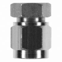
CONN JACK SMA END LAUNCH FIXTURE
Manufacturer
Emerson Network Power
Series
SMAr
Specifications of 140-0000-973
Accessory Type
End Launch Connector
Product
Crimping, Stripping & Cutting Tools & Drills
Description/function
Soldering Mating Fixture for SMA Jacks
For Use With/related Products
SMA Jacks
Lead Free Status / RoHS Status
Not applicable / Not applicable
Lead Free Status / RoHS Status
Not applicable / Not applicable, Lead free / RoHS Compliant
Other names
J10081


Emerson Network Power • Tel: 800.247.8256 • Fax 507.833.6287 • www.EmersonNetworkPower.com/connectivity
PC MOUNTING INSTRUCTIONS
High frequency end launch performance is dependent upon proper mounting. The following factors must be controlled
for optimum performance:
Figure 1
Figure 5
Figure 2
Figure 3
Figure 4
d. Use a minimal amount of solder between the contact pin and signal trace. Do not allow excess solder to build up
a. The connector should fit tightly against the circuit board edge, avoid gaps.
b. The center contact pin must lie parallel and flat against the circuit board, avoid gaps.
c. The contact pin should be centered on the circuit board signal trace.
e. Clean all excess flux and other residue from the launch area, especially between the trace and ground
or flow down the trace.
The basic steps required to mount the end launch connector to the circuit board are as follows:
High Frequency SMA End Launch Connectors
Mounting Instructions
1.
2.
3.
4. While ensuring the connector is held in the correct position, solder the
5.
6.
ground legs and/or ground posts to the top and bottom of the board prior to
bonding the center pin to the trace.
connector, which acts as a seal when soldering the center conductor pin to
the trace. Clamp the connector tightly against the edge of the board. This
action compresses the insulator seal against the board edge. This
effectively creates a barrier between the inner and outer conductors,
preventing the bridging of solder.
The fixture protects the connector from damage during clamping and also
maintains the proper location of the connector’s insulator and contact. To
use the fixture, thread the coupling nut on the mating end of the connector
and hand tighten. This mounting assembly can now be held in a vice or
similar clamping device, as shown in Figure 1.
aligned with the center of the signal trace as shown in Figure 2. Make sure
that the connector legs and contact pin are held flush against the top of the
circuit board, keeping the axis of the connector parallel to the plane of the
circuit board, as shown in Figure 3.
contact pin can be bonded to the trace by using a minimal amount of
solder as shown in Figure 4. It is important that solder flows along the
length of the exposed pin, creating a good electrical and mechanical
connection. Remove any excess solder that is not required for a solid joint.
A small amount of Teflon® insulation projects from rear mating plane of the
Once the connector body is properly grounded to the board, the center
Position connector on the circuit board, making sure the contact pin is
Fixture 140-0000-973 should be used as an aid during manual soldering.
side ground legs, as any flux present between the signal trace and ground
will affect performance. The completed mounting assembly should look
similar to the one shown in Figure 5.
Clean all flux and other residues from the trace area between the signal
7
Related parts for 140-0000-973
Image
Part Number
Description
Manufacturer
Datasheet
Request
R

Part Number:
Description:
TRANSDUCERS SPECTROL / 140-0-0 50 OHM 1 SECT
Manufacturer:
Vishay

Part Number:
Description:
POT 2.0K OHM WW SINGLE TURN
Manufacturer:
Vishay
Datasheet:

Part Number:
Description:
POT 10K OHM WW SINGLE TURN
Manufacturer:
Vishay
Datasheet:

Part Number:
Description:
POT 1.0K OHM WW SINGLE TURN
Manufacturer:
Vishay
Datasheet:

Part Number:
Description:
POT 5.0K OHM WW SINGLE TURN
Manufacturer:
Vishay
Datasheet:

Part Number:
Description:
AC/DC Front end 12Vo 36A 12Vsb Standard Airflow
Manufacturer:
Emerson Network Power

Part Number:
Description:
POWER SUPPLY DIN 24VDC 10A
Manufacturer:
Emerson Network Power
Datasheet:

Part Number:
Description:
POWER SUPPLY SGL 48VOUT 40W 3X5"
Manufacturer:
Emerson Network Power
Datasheet:

Part Number:
Description:
POWER SUP MED&ITE 48V 45W 2"X4"
Manufacturer:
Emerson Network Power
Datasheet:

Part Number:
Description:
POWER SUPPLY 60W 12V OUT
Manufacturer:
Emerson Network Power
Datasheet:

Part Number:
Description:
POWER SUPPLY 60W 48V OUT
Manufacturer:
Emerson Network Power
Datasheet:

Part Number:
Description:
POWER SUPPLY 60W 15V OUT
Manufacturer:
Emerson Network Power
Datasheet:

Part Number:
Description:
POWER SUPPLY TRPL 3.3/5/12V 40W
Manufacturer:
Emerson Network Power
Datasheet:

Part Number:
Description:
POWER SUPPLY SWITCHER 24V 40W
Manufacturer:
Emerson Network Power
Datasheet:

Part Number:
Description:
Linear & Switching Power Supplies 24V output 25W 2A Medical &Non-Medical
Manufacturer:
Emerson Network Power
Datasheet: