140-0000-973 Emerson Network Power, 140-0000-973 Datasheet - Page 3
140-0000-973
Manufacturer Part Number
140-0000-973
Description
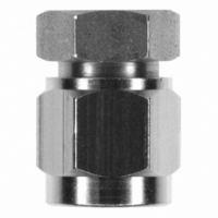
CONN JACK SMA END LAUNCH FIXTURE
Manufacturer
Emerson Network Power
Series
SMAr
Specifications of 140-0000-973
Accessory Type
End Launch Connector
Product
Crimping, Stripping & Cutting Tools & Drills
Description/function
Soldering Mating Fixture for SMA Jacks
For Use With/related Products
SMA Jacks
Lead Free Status / RoHS Status
Not applicable / Not applicable
Lead Free Status / RoHS Status
Not applicable / Not applicable, Lead free / RoHS Compliant
Other names
J10081


Emerson Network Power • Tel: 800.247.8256 • Fax 507.833.6287 • www.EmersonNetworkPower.com/connectivity
This connector is an economical alternative to other high frequency designs in the industry. This patent
pending design differentiates itself from other launch connectors:
• Design of the connector is self contained, no external mounting screws, adapter sections, spring
• Center contact pin does not require special orientation to the surface of the circuit board. The cen-
• Output coax of the connector at board launch is sized appropriately to match the thickness of the
• Signal side grounding legs of the connector are spaced close enough to keep grounding paths
• Signal side grounding legs and GCPW geometry control radiation, no additional shielding is
• Connector is not locked into position when placed on the circuit board. Intentional floating design
• The new distinctive through hole mounting technique allows the use of one connector with varying
• A small amount of PTFE insulation projects from the rear mating plane of the connector, acting as
• Appropriate sized connectors do not require additional compensation to standard coplanar or
clips, etc. are required for assembly to the circuit board.
ter contact is mechanically captivated and optimized to maintain proper impedance while with-
standing torque and axial force stress.
high frequency board substrate. The output coax section extends well within the connector while
maintaining constant inner and outer coaxial diameters.
short, but far enough apart to maintain constant impedance in the launch transition area.
required to prevent signal cross-talk effects in the transition area. The launch transition is effec-
tively isolated from adjacent transmission lines in the signal plane.
allows proper alignment in X, Y and Z, minimizing discontinuities due to manufacturing tolerances.
circuit board thicknesses. The connectors are also available in a traditional straddle mount end
launch design, which was pioneered by Emerson Network Power Connectivity Solutions over 20
years ago.
a seal when soldering the center conductor pin to the trace. The connector is held against the cir-
cuit board edge during the soldering process, compressing the PTFE insulation. This effectively
creates a barrier between the inner and outer conductors, preventing the bridging of solder.
microstrip matched impedance line geometries. Transition can be fine-tuned by pulling the trace
back a slight amount from the board edge.
Design Features
High Frequency SMA End Launch Connectors
3
Related parts for 140-0000-973
Image
Part Number
Description
Manufacturer
Datasheet
Request
R

Part Number:
Description:
TRANSDUCERS SPECTROL / 140-0-0 50 OHM 1 SECT
Manufacturer:
Vishay

Part Number:
Description:
POT 2.0K OHM WW SINGLE TURN
Manufacturer:
Vishay
Datasheet:

Part Number:
Description:
POT 10K OHM WW SINGLE TURN
Manufacturer:
Vishay
Datasheet:

Part Number:
Description:
POT 1.0K OHM WW SINGLE TURN
Manufacturer:
Vishay
Datasheet:

Part Number:
Description:
POT 5.0K OHM WW SINGLE TURN
Manufacturer:
Vishay
Datasheet:

Part Number:
Description:
AC/DC Front end 12Vo 36A 12Vsb Standard Airflow
Manufacturer:
Emerson Network Power

Part Number:
Description:
POWER SUPPLY DIN 24VDC 10A
Manufacturer:
Emerson Network Power
Datasheet:

Part Number:
Description:
POWER SUPPLY SGL 48VOUT 40W 3X5"
Manufacturer:
Emerson Network Power
Datasheet:

Part Number:
Description:
POWER SUP MED&ITE 48V 45W 2"X4"
Manufacturer:
Emerson Network Power
Datasheet:

Part Number:
Description:
POWER SUPPLY 60W 12V OUT
Manufacturer:
Emerson Network Power
Datasheet:

Part Number:
Description:
POWER SUPPLY 60W 48V OUT
Manufacturer:
Emerson Network Power
Datasheet:

Part Number:
Description:
POWER SUPPLY 60W 15V OUT
Manufacturer:
Emerson Network Power
Datasheet:

Part Number:
Description:
POWER SUPPLY TRPL 3.3/5/12V 40W
Manufacturer:
Emerson Network Power
Datasheet:

Part Number:
Description:
POWER SUPPLY SWITCHER 24V 40W
Manufacturer:
Emerson Network Power
Datasheet:

Part Number:
Description:
Linear & Switching Power Supplies 24V output 25W 2A Medical &Non-Medical
Manufacturer:
Emerson Network Power
Datasheet: