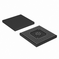
LH79524N0F100A1;55 NXP Semiconductors, LH79524N0F100A1;55 Datasheet - Page 54

LH79524N0F100A1;55
Manufacturer Part Number
LH79524N0F100A1;55
Description
IC, 32BIT MCU, 76.205MHZ, LFBGA-208
Manufacturer
NXP Semiconductors
Series
BlueStreak ; LH7r
Datasheet
1.LH79524N0F100A155.pdf
(64 pages)
Specifications of LH79524N0F100A1;55
Controller Family/series
(ARM7)
No. Of I/o's
108
Ram Memory Size
16KB
Cpu Speed
76.205MHz
No. Of Timers
3
No. Of Pwm Channels
3
Digital Ic Case Style
LFBGA
Core Size
32 Bit
Core Processor
ARM7
Speed
76.2MHz
Connectivity
EBI/EMI, Ethernet, I²C, IrDA, Microwire, SPI, SSI, SSP, UART/USART, USB
Peripherals
Brown-out Detect/Reset, DMA, I²S, LCD, POR, PWM, WDT
Number Of I /o
108
Program Memory Type
ROMless
Ram Size
16K x 8
Voltage - Supply (vcc/vdd)
1.7 V ~ 3.6 V
Data Converters
A/D 10x10b
Oscillator Type
External
Operating Temperature
-40°C ~ 85°C
Package / Case
208-LFBGA
Processor Series
LH795
Core
ARM7TDMI-S
Data Bus Width
32 bit
Mounting Style
SMD/SMT
3rd Party Development Tools
MDK-ARM, RL-ARM, ULINK2
Lead Free Status / RoHS Status
Lead free / RoHS Compliant
For Use With
SDK-LH79524-10-3216R - KIT DEVELOPMENT ZOOM SDK LH79524460-3474 - KIT DEV ZOOM STARTER FOR LH79524568-4305 - BOARD EVAL FOR LH79524
Eeprom Size
-
Program Memory Size
-
Lead Free Status / Rohs Status
Details
Other names
568-4332
935285053557
LH79524N0F100A1
935285053557
LH79524N0F100A1
LH79524/LH79525
Reset, Clock, and Power Controller
(RCPC) Waveforms
uses when coming out of Reset or Power On.
54
tOSC32
tOSC14
tRSTIH
tRSTIW
tRSTOV
tRSTOH
PARAMETER
Figure 37 shows the method the LH79524/LH79525
nRESETOUT
nRESETIN
XTAL32
XTAL14
nRESETOUT
VDDC
nRESETIN
Oscillator stabilization time after Power Up (VDDC = VDDCMIN)
Oscillator stabilization time after Power Up (VDDC = VDDCMIN) or
exiting STOP2
nRESETIN hold time after crystal stabilization
nRESETIN Pulse Width (once sampled LOW)
nRESETIN LOW to nRESETOUT valid
(once nRESETIN sampled LOW)
nRESETOUT hold relative to nRESETIN HIGH
VDDCmin
tOSC14
tRSTOV
DESCRIPTION
Table 18. Reset AC Timing
Figure 38. External Reset
NXP Semiconductors
Figure 37. PLL Start-up
Rev. 01 — 16 July 2007
tRSTIH
tOSC32
tRSTIW
tRSTOH
gives the timing parameters.
Figure 38 shows external reset timing, and Table 18
tRSTOH
MIN.
200
2
TYP.
Preliminary data sheet
3.5
1
System-on-Chip
MAX.
550
2.5
LH79525-22
LH79525-23
HCLK
HCLK
HCLK
UNIT
ms
ms
µS


