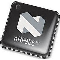
NRF9E5 NORDIC SEMICONDUCTOR, NRF9E5 Datasheet - Page 4

NRF9E5
Manufacturer Part Number
NRF9E5
Description
TRX, 430-928MHZ, MCU/ADC/PWM, SMD
Manufacturer
NORDIC SEMICONDUCTOR
Datasheet
1.NRF9E5.pdf
(108 pages)
Specifications of NRF9E5
Receiving Current
12.5mA
Transmitting Current
30mA
Data Rate
50Kbps
Frequency Range
430MHz To 928MHz
Modulation Type
GFSK
Rf Ic Case Style
QFN
No. Of Pins
32
Supply Voltage Range
1.9V To
Lead Free Status / RoHS Status
Lead free / RoHS Compliant
Available stocks
Company
Part Number
Manufacturer
Quantity
Price
Company:
Part Number:
NRF9E5C
Manufacturer:
NORDIC
Quantity:
5 000
Part Number:
NRF9E5C
Manufacturer:
NORDIC
Quantity:
20 000
PRODUCT SPECIFICATION
nRF9E5 Single Chip Transceiver with Embedded Microcontroller and ADC
12
13
14
15
16
17
18
19
20
21
22
23
24
25
Main office: Nordic Semiconductor ASA - Vestre Rosten 81, N-7075 Tiller, Norway -Phone +4772898900 - Fax +4772898989
Revision: 1.3
11.8
11.9
11.10
12.1
12.2
12.3
12.4
12.5
15.1
15.2
15.3
15.4
15.5
15.6
15.7
15.8
16.1
16.2
16.3
16.4
16.5
16.6
16.7
17.1
17.2
18.1
18.2
18.3
18.4
18.5
18.6
18.7
18.8
18.9
21.1
21.2
21.3
21.4
21.5
Transceiver Subsystem Timing .......................................................................................42
SPI ...................................................................................................................................44
PWM ...............................................................................................................................45
Interrupts .........................................................................................................................46
LF Clock Wakeup Functions and Watchdog...................................................................53
Power Saving Modes.......................................................................................................59
Microcontroller................................................................................................................62
Package Outline...............................................................................................................94
PCB Layout and Decoupling Guidelines ........................................................................96
Application Examples .....................................................................................................97
Absolute Maximum Ratings..........................................................................................104
Glossery of Terms .........................................................................................................105
Definitions .....................................................................................................................106
Your Notes ....................................................................................................................107
ADC – Configuration Register Contents ....................................................................41
ADC – Data Register Contents ...................................................................................41
Device Switching Times .............................................................................................42
ShockBurst
ShockBurst
Preamble .....................................................................................................................43
Time On Air ................................................................................................................43
Interrupt SFRs .............................................................................................................46
Interrupt Processing ....................................................................................................49
Interrupt Masking........................................................................................................49
Interrupt Priorities .......................................................................................................49
Interrupt Sampling ......................................................................................................50
Interrupt Latency.........................................................................................................51
Interrupt Latency from Power Down State. ................................................................51
Single-Step Operation .................................................................................................52
The LF Clock ..............................................................................................................53
Tick Calibration ..........................................................................................................53
RTC Wakeup Timer....................................................................................................54
Programmable GPIO Wakeup Function .....................................................................54
Watchdog ....................................................................................................................55
Programming Interface to Watchdog and Wakeup Functions ....................................55
Reset............................................................................................................................57
Standard 8051 Power Saving Modes ..........................................................................59
Additional Power Down Modes..................................................................................60
Memory Organization .................................................................................................62
Program Format in External EEPROM.......................................................................63
Instruction Set .............................................................................................................64
Instruction Timing.......................................................................................................70
Dual Data Pointers ......................................................................................................70
Special Function Registers..........................................................................................71
SFR Registers Unique to nRF9E5 ..............................................................................75
Timers/Counters..........................................................................................................76
Serial Interface ............................................................................................................83
Differential Connection to a Loop Antenna................................................................97
PCB Layout Example, Differential Connection to a Loop Antenna...........................99
Single Ended Connection to 50 Antenna ...............................................................100
PCB Layout Example, Single Ended Connection to 50 Antenna ..........................102
Configure the Chip as nRF905..................................................................................103
Status Register Contents .........................................................................................41
TM
TM
TX Timing ...........................................................................................42
RX Timing...........................................................................................43
Page 4 of 108
June 2006


